HSK Leads the Way
HSK Leads the Way
HSK toolholders were designed with high-speed machining in mind. This article explains the features of the toolholder that make it perform well in modern machining centers at high spindle rpm. It also discusses the toolholder's handling and maintenance requirements.
Many toolholder manufacturers are hailing HSK as the tool/spindle connection of the future.
Standard tapers still dominate today's toolholding market, but perhaps not for long. With the growth of high-speed machining, the short, hollow HSK taper is making its way into more and more U.S. machine shops. The development and use of HSK have been driven by the need for toolholders that can match the productivity of modern machine tools, which produce parts much faster than older machines do thanks to CNCs, high-speed spindles, preloaded spindle bearings, and automatic toolchangers.
It's not hard to understand why HSK is becoming popular in machine shops seeking to reduce cycle times. Current standard-taper toolholder styles such as CAT V-flange, BT, and NMTB have severe limitations in high-speed machining applications. In comparison, HSK toolholders provide superior rigidity and repeatability at aggressive cutting parameters. HSK's shorter, more gradual taper helps prevent the holder from pulling out of the spindle at high speeds. And since the toolchanger arm doesn't have to pull the HSK shank out as far as it would a standard-taper shank to clear the spindle, HSK holders can reduce the time for changing tools by 75%.
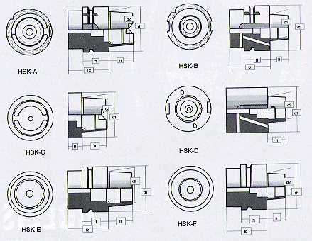
The use of HSK assemblies has been growing significantly since 1993, when DIN (the German standardization organization) issued the HSK shank standard, DIN 69893, for the six forms of the design (Figure 1). While most of these forms are considered specials, forms A and C are manufactured in Germany as stock standard styles, and the International Organization for Standardization (ISO) and the American National Standards Institute (ANSI) will probably use these forms as the basis for their HSK standards. Certain manufacturers sell versions of HSK toolholders that are proprietary and do not conform to any currently recognized standard. Although there is some variation in the HSK styles available, some generalizations can be made about the features of the HSK design and the benefits it offers users.
Clamping Forces
HSK spindles clamp tools with greater and more consistent force than most standard-taper spindles do. CAT and BT spindles generally depend on a pack of belleville spring washers for axial retention forces. (NMTB spindles use a mechanical drawbar and an internal shank thread.) At high spindle speeds, a spring-activated retention assembly doesn't offer much security.
Because the spring pack is compressed with every tool change, it tends to lose its resiliency. This reduces the total clamping force and can eventually lead to failure of the spring pack. Furthermore, the clamping forces applied by a standard-taper spindle are only axial, which will cause distortion of the toolholder with repeated use.

Figure 1: The six forms of the HSK toolholder shank, as defined by DIN 69893.
An HSK spindle's hydraulic retention assembly provides higher, longer lasting clamping force than a spring-activated assembly does. The retention claws of an HSK spindle apply consistent radial and axial clamping forces to the holder. Because the positive locking action is enhanced by centrifugal force, the retention claws hold the toolholder more securely at higher speeds.
The coefficients of thermal and centrifugal growth can produce undesirable results in standard-taper toolholders and spindles. The walls of a standard-taper holder are much thicker than the spindle walls. This difference can cause the spindle walls to expand more than the toolholder walls as heat and centrifugal force act on them at high speeds. Therefore, at high spindle speeds, a significant loss of rigidity occurs due to the lack of surface contact between the toolholder and the spindle.
The coefficients of thermal and centrifugal growth of an HSK holder's hollow, thin-wall shank more closely approximate those of the spindle. As a result, the two surfaces remain in contact even at high speeds. While a standard-taper holder may become loose and chatter inside the spindle, HSK (and NMTB) holders are mechanically locked into position.

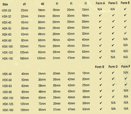
Table 1: The dimensions of HSK toolholder forms A, C and E (top) and forms B, D, and F (bottom). A check mark indicates standard sizes; N/A indicates sizes not in the standard.

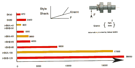
Figure 2: The total bending moment (a result of the force divided by the amount of deflection) allowed on a test bar by various shank sizes of standard-taper (SK) and HSK toolholders.
Full Flange Contact
An HSK assembly also owes its rigidity to its simultaneous-fit design. This means the toolholder's flange face contacts the spindle's face at the same time the taper is completely drawn into position. Because the toolholder is 0.00025" shorter than the spindle socket, an interference fit occurs at the toolholder's flange face. The resulting axial force, or mechanical preload, between the flange face and the spindle ensures full contact of the mating surfaces. This increased bearing surface area gives HSK holders better resistance to radial deflection than standard-taper holders have.
The largest diameter of contact between the toolholder and the spindle is most subject to radial forces. This cross section of the spindle/toolholder assembly is where the greatest bending moment occurs. With standard-taper holders, this cross section is the gage-line diameter of the taper. With HSK holders, however, the greatest bending moment occurs at the flange diameter. For example, a CAT V-flange holder with a No. 40 taper has a 1.750" gage-line diameter. As shown in Table 1, an HSK-A-50 holder has a 1.968" (50mm) flange diameter (d1), but only a 1.496" (38mm) gage-line diameter (d2). The HSK design incorporates a larger bearing surface area while utilizing a smaller gage-line diameter. The result is a smaller, lighter toolholder that requires less time in the tool-change cycle. HSK's improved resistance to radial loads allows for higher feed rates, especially during milling and other operations that subject the toolholder to great radial forces; HSK milling toolholders are significantly more rigid than standard-taper holders (Figure 2).
Gage Length
Because there has been no standard regarding a qualified gage length, variations up to ±0.020" are not uncommon in standard-taper toolholders. HSK toolholders have much better repeatability than standard-taper holders, because the flange-face contact ensures that the tolerances always remain the same. HSK form A holders offer radial and axial repeatability of 0.000098" in all three axes.
The HSK holder's flange-face contact also ensures consistent gage length, regardless of the machine in which it is used. The holder's length preset changes only when a new tool is put into it. This design feature benefits a machine shop's tooling-management program. Because the gage length is the same from one holder to the next, it is no longer necessary to program new presets for each toolholder. With a good tool-management program, a shop can ensure that tool diameters and lengths will always be consistent within a predetermined step after regrind. Diameter and length presets can be programmed only once, and the tool/toolholder assembly will be identical in both diameter and length each time it is assembled. This can improve piece-to-piece quality, reduce the time needed to load presets, improve confidence in preprogrammed clearances, and reduce tooling inventory.
Torque Transmission
Because a standard-taper spindle contacts the toolholder only at the gage-line diameter, the friction at this point aids only moderately in the transmission of torque. Torque is mainly transferred by the contact between the spindle's drive keys and the holder's drive-key slots.
An HSK spindle and toolholder, however, transmit torque by four methods. The drive keys and drive-key slots provide one method of torque transmission. These slots are located in the rear of the taper on forms A and C and in the flange on forms B and D. (Forms E and F have no drive-key slots, because they are designed to be truly symmetrical.)

Figure 3: HSK components used in modular tooling for machining centers.
Another method of transferring torque involves the HSK spindle's retention claws. The higher radial forces established by the retention claws increase friction and thereby aid in torque transmission.
The friction established by the preload between the flange face and the spindle, combined with the contact between the mating tapers, also helps transmit torque. With both radial and axial retention forces, the HSK assembly provides a superior friction lock by increasing total surface contact between the mating tapers.
Modular Design
HSK toolholders can be used in modular tooling systems similar to MVS and ABS. All HSK forms are well-suited for this purpose; however, forms C and D are specifically designed to increase a tool assembly's length using extensions or reducers (Figure 3).
The use of HSK's modular design is not limited to one type of machine tool. Different shank sizes can be used in a variety of machine tools. Standard-taper holders are currently used only in mills and boring machines; the large size and poor repeatability of these holders make them unsuitable for use in grinders, lathes, or honing machines. HSK holders, however, can be used in mills, boring machines, grinders, lathes and turning centers, and many special-application machines. By having one toolholding system for all types of machine tools, a shop can greatly improve its overall tooling-management program.
HSK Tips
The HSK design offers many advantages, but users must make a few special provisions to reap all the benefits.
Keep it cool. All HSK assemblies provide through-the-spindle coolant. Forms A, C, E, and F provide coolant directly through the center of the holder. Forms B and D provide coolant through the rear of the flange. Because the coolant changes direction in forms B and D, it cannot be applied at the maximum pressure and flow rate; the psi and gpm need to be modified. Therefore, the use of these HSK holders can be problematic in indexable drilling and other operations that require high-velocity coolant application.
HSK users also should consider a spindle-cooling system. Due to the excessive heat generated by high-speed machining operations, it will probably be necessary to have a cooling system for the HSK spindle. The system will help extend spindle-bearing life, reduce thermal expansion, and improve the performance of the spindle and toolholder.
Keep it clean. When using HSK assemblies, it is especially important to keep the work environment clean. The simultaneous fit between the flange face and the spindle makes the HSK toolholder and spindle more vulnerable than standard-taper assemblies to contamination by chips and debris. Due to the tight tolerances of the mating surfaces, contaminants will significantly shorten the life of the HSK spindle and toolholder. Piece-to-piece quality can suffer as dimensions begin to vary. Contaminants between the flange surfaces will reduce concentricity and surface contact by causing the toolholder to tilt slightly.
To avoid the detrimental effects of contamination, the tools, the toolholders, and the spindle must be kept clean during normal operating conditions. All tool shanks should be wiped clean before they are mounted into the tool magazine. When tools are not in use, they should be stored in a toolroom or shielded in some way from the working area. The spindle should have provisions to clean itself and the tool during a tool change; a blast of air through the spindle blows contaminants away from the spindle ID and the toolholder.
Keep it balanced. HSK toolholders typically are used at high speeds, because their design is so well-suited to this type of machining. Users must realize that the need for properly balanced tools rises with the increase in rpm. To correctly balance their tools, users must understand what Q quality means in the context of balance specifications.
All dynamic objects have a certain amount of vibration or imbalance. Q quality is a hypothetical value that quantifies the inherent imbalance of a dynamic or rotating tool. Generally, this value is Q2.5 for rotating tools.
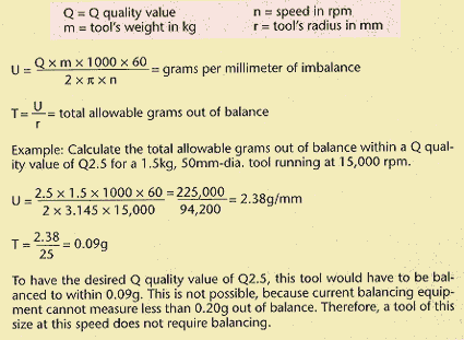
Q quality is not the same as what the ISO 1290 G standard refers to as grams per millimeter (g/mm) of imbalance. For example, a tool rated at Q2.5 is not 2.5g/mm out of balance. As shown by the first formula in Figure 4, the tool's imbalance in g/mm ("U") is derived from the Q quality value ("Q"), the tool's weight in kg ("m"), and the speed in rpm ("n").

Figure 4: The formulas necessary to calculate tool imbalance within the desired Q quality level.
Users cannot bring their tools any closer to perfect balance than the accuacy of the balancing equipment will allow. Current equipment balances to an accuracy of 0.20g. Up to now, this degree of accuracy has been more than sufficient. As shown by the second formula in Figure 4, the total allowable grams out of balance ("T") within the desired Q quality value is calculated by dividing the tool's imbalance in g/mm ("U") by the tool's radius in mm ("r").
As the rpm increases, the maximum grams a tool can be out of balance decreases. Because tools can only be balanced to an accuracy of 0.20g, tool imbalance doesn't become a problem unless the total grams of imbalance ("T") is equal to or greater than 0.20g. If "T" is less than 0.20g, the tool generally doesn't require balancing.
About the Author
Patrick Manthey is sales and marketing manager of the Wohlhaupter products group of Dapra Corp., Bloomfield, CT.


