Hydro power
Hydro power
While hydraulic toolholders are said to have limited applications, their high gripping force and simple operation help them secure a place in machine shops.

Courtesy of Matthew Panosh/Schunk
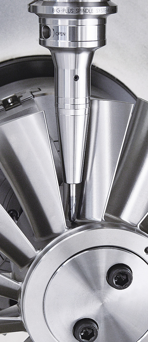
A Schunk CAT40 TENDO Platinum hydraulic toolholder used in a finish milling application.
While hydraulic toolholders have been around for many years, there's still a good deal of debate about their utility. Advocates extol the extremely tight TIR, crushingly high gripping force and simple operation of hydraulic holders, while detractors say they are expensive and limited to certain applications. The detractors instead tout the versatility and dependability of other toolholding methods. Ultimately, it's up to the individual machine shop to decide if they are an effective choice.
To Have and to Hold
"Hydraulic toolholding technology … really took a strong hold, especially in the automotive industry, around the turn of the 1980s," said Alan Miller, engineering manager at BIG Kaiser Precision Tooling Inc., a Hoffman Estates, Ill.-based manufacturer of tooling and toolholders. Compared to collet chucks, with their array of parts, he noted, hydraulic holders are easier to change and provide consistent runout. "People realized that, for large production runs, they were the way to go."
In contrast to mechanical chucks, hydraulic toolholders are simple to set up: The operator just inserts the tool and turns the actuation screw. That screw causes a piston to push hydraulic fluid into the bladder surrounding the tool shank, compressing the thin metal wall evenly around either the sleeve or directly around the tool shank, providing gripping forces of up to 900 newtons.
According to Matthew Panosh, tooling group manager at Schunk Inc., Morrisville, N.C., Schunk hydraulic toolholders offer runout of 3µm or less measured at 2½ times the clamping diameter. "The real benefit of hydraulic toolholders is that they clamp the tool concentrically," he said. "You drop the tool in and turn the actuation screw to the dead stop. If you do that 10 times or 100 times, as long as the holder is in good shape, the runout value will be the same."
In addition to repeatability, hydraulic toolholders are repairable when individual components begin to wear or break. Schunk has repaired and replaced seals in holders up to 15 years old and returned them to full functionality, according to Panosh.
Origin Story
The origins of hydraulic toolholders date to the middle of the last century, according to Bob Andre, vice president of manufacturing at Hydra-Lock Corp., Mt. Clemens, Mich. "Hydraulically actuated part and tool holding first came on the market in 1947, with Hydra-Lock being an originator of much of the technology," Andre said, adding that Hydra-Lock patented some of that technology.
However, the role of hydraulic toolholders as a mainstay in some machine shops is more recent and owes much to the desire to overcome the limitations of other types of toolholders, according to Timothy Fara, managing director for Bilz Tool Co. Inc., Lombard, Ill. In the 1980s, he said, endmill holders were the predominant toolholders in the marketplace. Early collet chucks were too limiting, in that they were only suitable for drilling applications, and while the early 1990s saw the rise of single-angle collets like the Erickson TG (Tremendous Grip), which allowed for greater gripping strength and the ability to handle radial loads, they weren't ideal for all applications.
"One problem with the Erickson TG collets started when we began to push the feed rates to keep up with the jobs, which would cause the tools to move around," Fara said. "So, different types of collets were created to account for different types of jobs, which is when the hydraulic chuck really started to catch on."

Courtesy of Hydra-Lock
From left to right, a special flange-mounted hydraulic holder and two hydraulic holders with standard shank mountings.
The main advantage of hydraulic toolholders is their ability to securely grip the tool shank, which reduces TIR. "The industry was looking for lower TIR, something that would hold a cutting tool closer to the center line," Fara said. "The main reason for that is that for every 0.001 " the tool goes off center, you [immediately] sacrifice 10 percent of your tool life because chip load is no longer evenly divided amongst the flutes of the cutting tool. Whatever side is offset takes the brunt of the chip load, so wear is accelerated because there is more work being done by one side of the endmill than the other. Hydraulic toolholders, with their extremely tight TIR, were an answer to that."
Similar to other types of tooling, a variety of hydraulic toolholder classes are available. For example, Hydra-Lock offers three: Class A uses a solid-steel expanding sleeve, Class B uses a slit-steel expanding sleeve for greater expansion for a given pressure, and Class C uses the company's Hydra-Fibre plastic material in the sleeve and is for holding thin-walled and out-of-round parts or tools.
Schunk's TENDO series of hydraulic toolholders also is available in three different levels. The entry-level EC line, according to Panosh, is only available in sleevable diameters and not repairable. The Platinum line, made from through-hardened tool steel, is available in a range of sizes, both sleevable and direct-clamping. The Tech line consists of application-specific specials.
Alternative Nation
Despite their advantages, some toolholder manufacturers have stopped selling hydraulic units in favor of mechanical or thermal alternatives.
"About 8 years ago, we moved our toolholder focus almost exclusively to milling chucks," said Scot Irie, product manager at Lyndex-Nikken Inc., Mundelein, Ill. "Early hydraulic chucks had no shutoff system, which resulted in internal leakage of hydraulic fluid, so we transferred our efforts to milling chucks."
Courtesy of BIG Kaiser Precision Tooling
BIG Kaiser's Super Slim line of toolholders takes advantage of the low clearances available with hydraulic toolholders.
Nikken milling chucks utilize a mechanical bearing nut that clamps an internal sleeve, which in turn clamps the tool, essentially crush-forming the sleeve material to fit around the tool shank. "It works on a principle very similar to hydraulic chucking," Irie said, "but instead of using fluid dynamics, it's mechanical, so there's even more gripping force. Basically the only thing that's going to hold more securely is an endmill holder, which actually physically locks the tool into place."
According to Bilz's Fara, besides potential leakage, hydraulic toolholders have two other major drawbacks. One is the tool shank must be cylindrical and fully inserted into the holder—if there are any flats or voids, the hydraulic fluid will force the body of the toolholder into that space, and it may not expand properly, or the thin metal wall may begin to wear unevenly.
"The second issue with hydraulic chucks is that they're really for Z-axis machining only," Fara said. "If there's any radial load against the side of the tool, the fluid around the shank of the tool causes the cutting tool to cantilever inside of the chuck, causing the fluid to move from one side to the other. Besides increasing runout, movement inside the hydraulic chuck can cause fatigue on the steel wall and eventually cause cracks, which can render the holder unusable or change the size of the bore so that it won't have the same gripping strength deep in the bore as it does at the tip of the bore."
However, he added, hydraulic chucks are versatile tools for drilling and reaming and can fit into smaller clearances than an ER collet chuck. "Depending on the application, if you can overcome those negatives, the hydraulic chuck is a very good tool for your job."
Lyndex-Nikken's Irie agreed that, despite their limitations, hydraulic chucks have distinct advantages.
"The technology has obviously advanced since we stopped manufacturing [hydraulics]," he said. "Given that, I'd say the biggest advantage hydraulic chucks have over, for example, milling chucks is that they can fit the size of the workpiece. Clearance is a big issue, and the milling chuck has a large nut on the front end, which can be a major size limitation. Hydraulic chucks can maneuver into smaller spaces while maintaining good rigidity."
Chucks and Balances
Proponents of hydraulic toolholders argue that the technology's strengths outweigh its limitations. For example, according to BIG Kaiser's Miller, there are few maintenance concerns with hydraulic toolholders, so long as the bore is kept clean and the tool is properly applied. Also, while there is an upper speed limit of around 20,000 rpm on most hydraulic toolholders, because centripetal force can cause the hydraulic fluid to pull away from the tool shank, that limitation is offset by the inherent vibration-damping effect provided by surrounding the tool shank with fluid.
"Hydraulic chucks are really the best you can get for finish milling and reaming," Miller said, "and that's due both to the hydraulic fluid damping the vibration, which imparts finer surface finishes, and the tight runout, which provides accurate size and form." It's also useful when dealing with very high coolant pressures, he explained, because unlike other clamping systems with O-ring seals that can be pushed out at high pressure, the long clamping areas on hydraulic chucks remain sealed.

Courtesy of Matthew Panosh/Schunk
High clamping force and repeatability are major appeals of hydraulic toolholders like the Schunk TENDO Platinum line.
Despite the critics, Schunk's Panosh asserts that hydraulic chucks are more versatile than they're given credit for, especially when applied properly. "If you want to get the most benefit out of hydraulic toolholder, you probably want to direct-clamp the tool shank," he said. "For example, our TENDO EC is only available in sleevable sizes, but even when you're using a sleeve, you're concentrically clamping. The difference is the added tolerance that comes with the sleeve, so you get slightly more runout and less repeat accuracy. Direct clamping runout is 3µm or less; adding the sleeve is still 5µm or less.
"Hydraulic toolholders have been given a bad rap, but the reality is they are versatile enough to be used for any application," he continued. "You may get added benefits in, say, a milling application, if you were to sleeve as opposed to direct-clamp, because adding a sleeve is essentially thickening the wall of the toolholder and increasing the radial stiffness of the tool. There are some applications, like super-heavy roughing, where you might benefit from using a side-lock holder, but we are seeing the TENDO EC line used successfully even in roughing applications."
The decision to use hydraulic toolholders depends on the job and a shop's priorities. Critics call them one-dimensional or limiting, but the grip and accuracy hydraulic toolholders offer can't be ignored, and their small stature makes them ideal for jobs other toolholders simply can't fit into. Unlike shrink-fit assemblies, there's no need for an induction system to expand the bore, and, unlike collet systems, setup is practically effortless. While not ideal for every situation, hydraulic toolholders do the job they're designed for—and then some. CTE
Contributors
BIG Kaiser Precision Tooling Inc.
(847) 228-7660
www.bigkaiser.com
Bilz Tool Co. Inc.
(847) 734-9390
www.bilzusa.com
Hydra-Lock Corp.
(586) 783-5007
www.hydralock.com
Lyndex-Nikken Inc.
(847) 367-4800
www.lyndexnikken.com
Schunk Inc.
(800) 772-4865
www.us.schunk.com


