Lights on
Lights on
Quality Mould Inc., a maker of molds for glass products such as lamps and headlights, thrives by leveraging its skills and using advanced technology.
Quality Mould Inc., a maker of molds for glass products such as lamps and headlights, thrives by leveraging its skills and using advanced technology.
U.S. moldmaking has been hit hard by overseas competition. Makers of molds for glass products face added pressure because alternate materials—mostly plastics—are replacing many glass applications.
Learn more about glass molds and glassmaking
Quality Mould Inc., one of a handful of independent glass mold shops remaining in the U.S., machines molds for pressed-glass products. The shop combines traditional craftsmanship with CNC machining and CAM technology that set its products apart from those of overseas competitors. Quality Mould is also leveraging its longtime skills to diversify its customer base.
Founded in 1983 in Greensburg, Pa., and now located in Latrobe, Pa., Quality Mould has produced molds for pressed-glass products ranging from
Courtesy of B. Kennedy
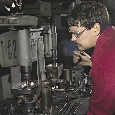
Keith Hoover, a machine operator at Quality Mould, operates a Deckel pantograph milling machine to remachine an aircraft lighting lens mold in the foreground, matching it to the one the machine is tracing in the background.
Courtesy of B. Kennedy
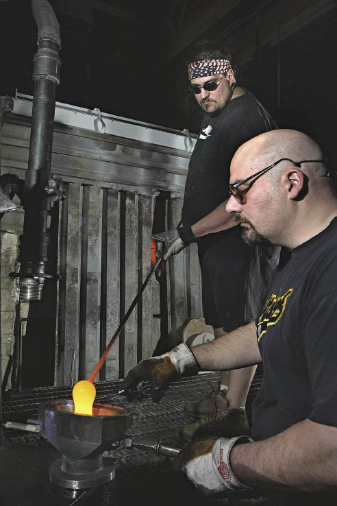
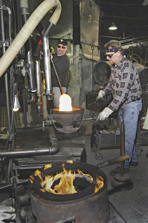
At Chromaglass, a glass products manufacturer, presser Art Theys (foreground) and gatherer Ernie Ryan use the mold machined by Quality Mould to make the lens.
Changes in material application have affected the glassmaking business. Bruce Stephens, president of glassware manufacturer Chromaglass Inc., Delmont, Pa., and a Quality Mould customer, said, "Obviously foreign competition has hurt," but added that alternate materials have also had a significant effect. Chromaglass manufactures clear and colored heat-resistant borosilicate glass.
Stephens cited the move to light emitting diodes that has increased the use of plastic lenses. "LEDs don't
Quality Mould takes full advantage of that market. For example, the company makes glass molds for highly contoured, precision glass lenses for landing lights and other applications on commercial and military aircraft. Tough, long-wearing molds for large-volume applications, such as headlight and spotlight lenses, are another specialty, as are molds for large specialty glass products.
"We probably do more big stuff than little stuff," said Quality Mould President D.J. Danko. "Everybody is sending us huge parts to cut, because we can. We just made a mold for a 24 "-dia. lens for lights on a movie set."
The shop recently purchased two machines to cut larger workpieces, a Mazak VTC 300 vertical machining center with X-, Y- and Z-axis travels of 65 ", 30 " and 26 ", respectively, and a Doosan Puma VT900 vertical turning center for parts up to 40 " in diameter. Many mold components, such as those for lighting applications, are round and involve turning. "Then, if it gets holes or slots, it will go into the mill," Danko said.
Reverse Engineering
Danko said one of Quality Mould's strengths is reverse engineering. "We can take a piece of glass, reverse engineer it, design a mold and copy it," he said.
For smaller pieces, the shop often uses digital scanning to create 3-D electronic files. Those files are exported to a SURFCAM CAD/CAM system to create mold machining programs. For larger complex parts, however, Quality Mould often collects dimensions by physically measuring plaster molds of the part.
Courtesy of B. Kennedy
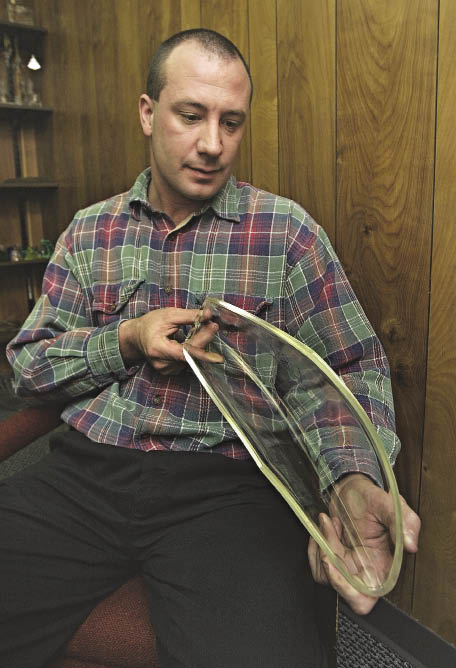
D.J. Danko examines a glass lens for an aircraft landing light that was formed in a pressed-glass mold designed and manufactured at Quality Mould.
One example is the process for a 28 "-dia., 8 "-tall mold for a glass light shade.The first step was making a plaster cast of the inside of the shade and cutting the cast in half vertically through the center. The resulting half-dome was centered on a large piece of paper. Scribing around the periphery, technicians measured and recorded the radii, angles and diameter of what would be the mold's plunger. Smaller casts also were made of the major details and measured.
"We can tell the programmer that a scallop is so deep, so wide, a certain height and a certain radius," said Barry Beveridge, vice president. "We can get the dimensions off a piece of paper as close as 0.005 " to the original piece."
A CAD/CAM programmer created a 3-D file of the part and generated machine code to cut the plunger. By measuring the thickness of the glass in the original shade, the shop calculated the dimensions of the mold cavity and translated them into a CAM program.
For other reverse engineering jobs, the shop makes a plaster mold of a part, casts a positive replica of the item, then casts a mold master from the replica in hard silicon-carbide-reinforced plastic. The plastic master mold is then traced with a vintage Deckel pantograph duplicating machine. The Deckel has two heads connected in parallel, one with a tracing probe and one with a milling spindle. As the operator traces the hard plastic mold master with the probe, the machine spindle, equipped with the appropriate cutting tool, cuts the metal mold that will form the glass product.
Nearness Counts
Beveridge said one of Quality Mould's clear advantages over offshore competition is proximity. "We work directly with the customer," he said. "We know exactly what is going to withstand the heat, what mold thicknesses are appropriate and what is going to press the best. If the customer makes changes in the middle of the process, we can do that immediately." In many cases, Quality Mould keeps semifinished molds in inventory and can finish them to customer specifications and deliver in a few days.
Hugh Reed, director of technical services at Kopp Glass, Pittsburgh, said the glassmaker shares many of Quality Mould's challenges and its approach to customer service. Kopp Glass focuses on low-volume, specialty glass products and colored glass products, serving a variety of markets from aerospace to industrial lighting applications and utilizing a wide range of colored and technical glass options. Kopp manufactures most of its molds in-house, "but for molds larger than our equipment can handle or for expedited delivery requests, we use Quality Mould," he said.
Courtesy of B. Kennedy
Presser Bob Humme (right) and gatherer Walt Grebner work together to press an architectural light cover from a mold at Kopp Glass. In the foreground, a burner keeps a ring component of the glass-pressing system hot and ready for the next pressing cycle.
Reed said interaction with customers throughout the design and glassmaking process is crucial. "We prefer customer involvement as early as possible in the design stage of the project. When possible, we can tweak the shape, the thicknesses, the tolerances or some of the design characteristics to give them the best price possible. There are many features of a glass lens that can be slightly modified to improve the glass flow and the forming process in general," Reed said. "Preferably, a customer supplies us with a basic 2-D drawing and an IGES file with a preliminary concept. Then we tweak it a bit and work with them to make it a manufacturable piece," he said. The staff at Quality Mould, he added, "understands what we are looking for and can help work out the details."
Danko reported that an unintended result of the offshoring trend is growing demand for repair and remanufacturing of faulty foreign molds. He said his shop generally "doesn't like to touch" such remedial work, but will handle it for a premium price. For example, Quality Mould attempted to rework a set of inaccurate molds that a glassmaker outsourced to an Asian supplier, supposedly to save $10,000. "We went to recut them and I checked the hardness; they weren't heat treated," Danko said. "They were supposed to be Inconel; we had them analyzed and they weren't even close to Inconel. Thirty thousand dollars worth of molds went into scrap."
Cost pressures drive Quality Mould to continuously boost productivity and minimize labor costs. The shop has 10 CNC mills and seven CNC lathes run by four operators on the first shift and three on the second shift. Operators are cross-trained to set up, program and run multiple machines and handle initial part checking. The shop typically programs parts off machine. "We download the programs to the machines through an Ethernet," said Danko. "That way, when machining is done, the operators have the program, the tools and the fixtures ready. It speeds throughput."
New Opportunities
Fundamental changes in Quality Mould's business, such as the declining use of glass, can't be overcome by excellent customer service or productivity initiatives. As a result, the shop is finding new ways to apply its equipment and well-developed skills.
Quality Mould recently started handling overflow of general machining for another shop that makes military parts. A typical job is a ¾ "×53 "×17 " A-656 steel axle plate for a Humvee that involved drilling and tapping 12 holes and machining a curved slot and a large hole. "The military part work is actually a step down for us," Danko said. "It is easy, because we are a multiaxis shop doing a lot of design work." The key to handling contract work, he said, is quickly developing a process within a target price.
Courtesy of B. Kennedy
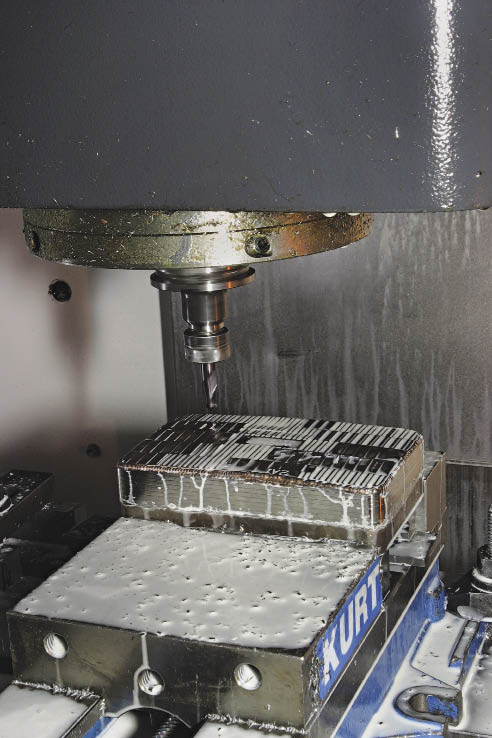
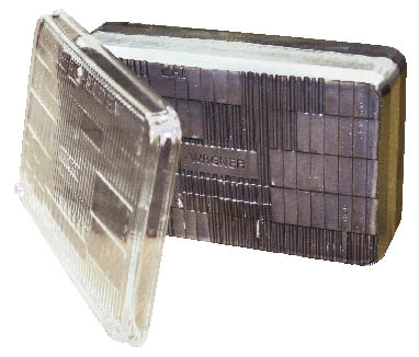
This detailed plunger, being milled from Inconel at Quality Mould, is used to press a replacement automotive headlight lens like the one shown.
Its enhanced ability to machine large parts also helps Quality Mould handle big jobs more efficiently. In processing large drive gears for Caterpillar Tractor Co., the shop's new large machines boost productivity. Before acquiring the Doosan VTL, Danko said, "We were machining the gears horizontally and only grabbing about 0.800 " of the part. We couldn't rip into it; it might throw the piece out of the machine. On a vertical lathe the weight of the part helps hold it down. More secure workholding enabled the shop to increase cutting parameters. "We pretty much cut the cycle time in half on the drive gears," Danko said.
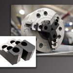
Finish machining and fine polishing are key moldmaking skills, and Quality Mould has applied those capabilities in a new way: drilling and polishing high-end automotive accessory wheels. Danko said the wheel makers "supplied us with a forged blank and we machined the different patterns." The wheels were then mounted on a chuck, sanded with progressively finer sandpaper grits and polished to a mirror finish with a buffing compound.
Work Is Where You Find It
Expanding the shop's customer base is a constant effort, said Danko. "We get hooked up with a lot of people through word of mouth; cutting tool salesmen and other suppliers go out and really push for us. They tell other manufacturers that our shop can do complex parts and offer a lot of throughput." Opportunities the shop is exploring include making power generation, mining and railway parts. Through a contact met at a military manufacturing trade show, the shop landed a contract to make parts for revamped naval vessels.
Manufacturing success is not determined by simply making good parts. Quality Mould is a prime example of a shop responding on a variety of fronts to survive and thrive in a global economic and technological landscape. CTE
About the Author: Bill Kennedy, based in Latrobe, Pa., is contributing editor for Cutting Tool Engineering. Contact him at (724) 537-6182 or by e-mail at [email protected].
Courtesy of Quality Mould
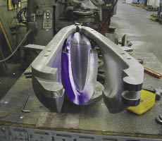
To permit a complex glass part such as an aircraft lens to release from the mold, the mold must often be made in sections that move apart and provide clearance.
The pressed-glass process: fast, precise and inexpensive
Pressed-glass techniques—in which a plunger presses a gob of molten glass into a mold—were developed in the early 1800s. The method provides a fast, precise and inexpensive way to manufacture glass products.
The pressed-glass process includes the mold, with a cavity that forms the glass item's outer features; a ring that fits on top of the mold; and a plunger that forms the interior of the glass product. A worker, called a gatherer, rolls a ball, or gob, of molten glass on the end of a rod. He carries the gob to the mold where the presser clips off the exact amount of glass needed to make the part with a large pair of scissors. The presser pushes the plunger into the mold. The plunger is guided by the ring, which stops glass from flowing past it and forms the edge of the part. After cooling, the glass part contracts slightly and is removed from the mold.
The main difference between molds for glass and plastic products is heat. While the melting points of various plastics range from about 250° to 700° F, molten glass typically melts at 2,300° F. A mold for plastic can be machined from aluminum, but pressed-glass molds are cast iron, stainless steel or even Inconel.
The mold for glass must withstand intense heat while maintaining a certain temperature range. If a mold is too hot, glass will stick to it; if it is too cold, the part will not hold its shape. Using air ducts on the pressing machine to cool the mold and plunger and a burner to heat the ring between molding operations, the presser keeps the molding system at a constant temperature. "It's a fine line; it takes a lot of skill," said Bruce Stephens of Chromaglass. "I don't know what's out there that uses this kind of skilled craftsmanship for a common, industrial-use product."
Mold material choice also depends on the volume of parts it will produce. "You get a lot more parts out of stainless steel, but it's more expensive than cast iron," said Danko of Quality Mould. His shop even makes molds for glass headlight lenses out of Inconel 718. "It lasts when they are pressing thousands and thousands of pieces," he said.
Stephens said surface finish requirements for the final glass part also affect material choice. "We found that stainless steel has a finer structure than cast iron and surface finish is better," said Danko. A rougher surface finish in the mold will be repeated in the glass product it forms. In a lens, that can cause light to scatter and reduce brightness.
Traditionally, designing molds for pressed-glass products involved a master mold hand-carved from plaster (see sidebar on page 34). "Basically, everything we get today is a 3-D model," said Danko. "The customer sends us a file and then we create the mold around it." Simplicity is the first priority. "You always try to make it in a block mold, with no joints or hinges," he said. However, to permit a complex part to release from the mold, the mold may need to be made in sections that move apart and provide clearance. The mold designer manipulates the 3-D model and "keeps playing around with it and aligning it, trying to open it in a two-piece mold," Danko said, noting that some complex products require three- or four-part molds.
Multiple mold components magnify manufacturing challenges. "Molds aren't a monolithic temperature; you have to adjust their design for expansion," said Stephens. Hinged molds are more even complex. And glass distorts as it shrinks and cools. "Part of what we've learned to do with Quality Mould is utilize their computer technology to try to outguess what the shrinkage is going to be," said Stephens. "And we're actually pretty close."
Barry Beveridge of Quality Mould said tolerances on molds for pressed-glass parts typically are 0.005 " to 0.010 ", but for higher-precision products such as headlight lenses, "it's pretty much 0.001 " tolerance all around." Surface finish depends on the application; typical molds require a 20 µin. Ra finish, but others such as bottles specify a 2L mirror finish, achieved by polishing after machining. "We machine as close as we can to a mirror finish, but there are always tool marks," he said.
In general, molds are machined and heat treated in a sequence determined by the mold's configuration and the volume of parts it will produce. Molds for aircraft lenses, for example, are not heat treated because volume is small, at most in the hundreds. On the other hand, Inconel molds for spotlights and floodlight lenses receive heat treatment that enables them to endure runs in the thousands.
Whether a mold will be machined after heat treating depends on its structure and tolerances. "If it is a thick, heavy mold, we machine it complete because there is minimal chance the heat treatment will distort the mold," Danko said. On the other hand, "if the mold has close tolerances and a thinner wall, then we rough it down, leave about 0.050 " stock and finish it after heat treating."
The depth of mold cavities and possible interference with the mold walls can influence tooling choice. Danko said Quality Mould tries to keep tools as short as possible, but deep cavities may require long collet holders. The shop recently invested in holders from Techniks Inc., Indianapolis, in which the collet is tightened with a drawbar through the back end of the holder, eliminating the use of a collet nut that can create clearance problems with the mold cavity walls.
For deep molds, cutting parameters change as well. "We run a lot slower," Danko said. "Some of these tools are hanging out 18 ". The operator will figure out what length of tool fits, then determine how fast to run it."
—B. Kennedy
Courtesy of B. Kennedy
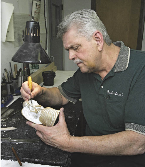
Quality Mould's Barry Beveridge demonstrates how a 3-D master for a decorative glass item was carved from a plaster blank.
Carved by Hand
A disappearing but still—valuable skill is hand carving of mold masters. Working from a 2-D sketch or a customer's idea, Quality Mould's Barry Beveridge hand carves a 3-D item from a plaster blank. A master mold is then made of the item, and that master is then traced to machine the actual mold. Beveridge said he began carving as a child, apprenticed in a mold shop hand carving bottle molds then was hired by a mold shop (his former employer) to work in the engineering department carving models. About 4 years ago, he said, demand for hand carving "came to a screeching halt," mostly due to the increasing accuracy of laser scanning and CAD programs. "Every once in a while, we still get jobs where I have to do some model work," he said, adding that it remains a satisfying and productive pursuit.
—B. Kennedy
Contributors
Chromaglass Inc.
www.chromaglass.net
(724) 468-5519
Kopp Glass Inc.
(412) 271-0190
www.koppglass.com
Quality Mould Inc.
(724) 532-3678
www.qualitymouldinc.com