Once only employed when other part-making methods failed, metal-injection molding (MIM) has matured to become the process of choice in many applications.
“MIM used to be the last resort for making parts and was used only when the part couldn’t be made any other way,” said Jim Adams, vice president, technical services for the Metal Powder Industries Federation (MPIF), parent of the Metal Injection Molding Association (MIMA), Princeton, N.J. “But the technology is at a level where many parts are now being designed for MIM, such as hearing aid components, surgical tools, automotive turbocharger components and brackets for braces. Today, more multiple-machined part assemblies are being replaced with a single MIM part, reducing energy, assembly time and, ultimately, cost.”
MIM can produce high-volume, high-precision components for a range of industries. Its use is growing in the manufacture of medical devices, firearms, automotive parts, dental devices, electronic packages, cutting tools and other industrial parts.
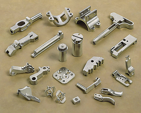
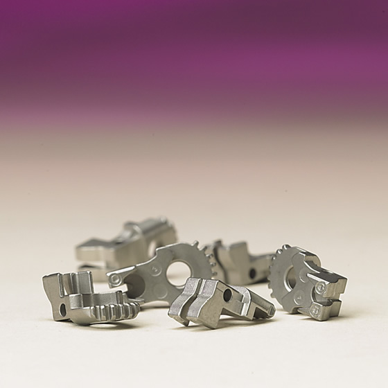
Courtesy of Megamet Solid Metals
An array of parts made via metal-injection molding.
In its annual members-only PM Industry Pulse Survey, MIMA asked its members in what North American markets they are seeing most of their products used. Last year, firearms and medical were the two primary areas, with roughly 25 percent of the market for each, followed by automotive at around 15 percent, dental at less than 5 percent, electronics at less than 5 percent and telecom at 1 percent, with the remaining percentage being general industrial applications, according to Adams.
The percentage for auto, however, may not trail the leaders for long. “The automotive industry is where the largest untapped opportunities remain for the North American MIM industry,” said Bruce Dionne, president of MIMA and general manager of Megamet Solid Metals Inc., Earth City, Mo., which produces MIM components.
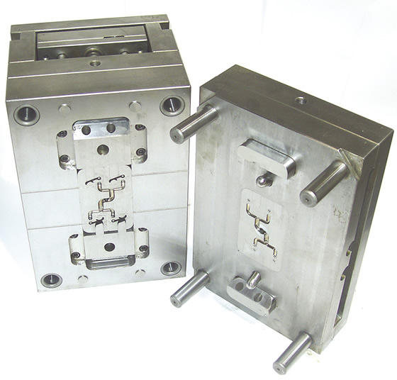
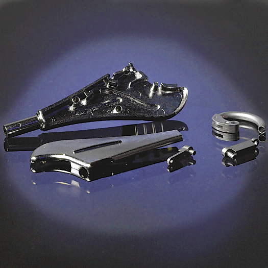
Courtesy of Megamet Solid Metals
A typical mold Megamet uses to make MIM parts.
One area where Randall M. German sees growth is implantable medical devices. German is professor of mechanical engineering at San Diego State University and a noted MIM expert. “The innovators are doing implants, not just the hand tools,” he said. “MIM is going into bone reconstruction, heart valves and implantable hearing aids. Hot new topics are advanced surgical stapling devices and small robotic manipulators that use MIM parts for linkages.”
In North America, stainless steel is by far the most common MIM material, accounting for about 45 percent of the total, according to Adams, with steel in second at 30 percent. Soft magnetic materials are significant at 10 percent, but tungsten, nickel, titanium and aluminum are each used in only about 1 percent of applications.
“Titanium is very difficult to process,” Dionne said. “It has a strong affinity for oxygen and as a result it is hard to maintain a pure titanium grade throughout all phases of production. Some companies are doing it successfully, but in very low quantities in specialty applications.”
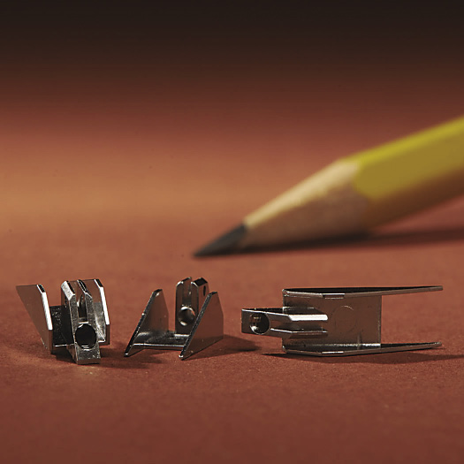
Courtesy of Metal Powder Industries Federation
A stainless steel shuttle used in a “smart” stapling device for arthroscopic surgery is made via MIM. The 5g shuttle has two components that previously were combined via laser welding. Secondary operations are reaming and tapping the small hole.
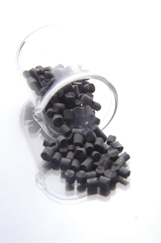
Courtesy of Ryer
Ryer’s 17-4 PH D90-8 powder metal is suitable for molding MIM parts.
Another material challenging to work with is aluminum. “It is difficult to sinter and so the process has to be done precisely,” said Ron Peterson, vice president of Ryer Inc., Temecula, Calif., a MIM feedstock supplier. “But it is good for components that are weight-sensitive and parts subjected to elevated temperatures where plastic can’t be used.”
The MIM process involves mixing metal powders with thermoplastic binders to form a feedstock that is injection-molded using standard plastic injection-molding machines.
After ejection from the mold, the binders are removed (see page 66). The parts are then sintered at a temperature high enough to create metallurgical bonds between the powder particles, but below the melting point of the metal.
During the sintering process, the parts typically shrink 15 to 22 percent, depending on the debinding system used, to achieve the final component density of 96 to 98 percent of the full-density solid metal (2 to 4 percent porosity).
Small World
MIM’s strengths lie in high-volume production of small, complex parts. Tooling and setup costs are difficult to justify for low-volume work, so MIM works best for production quantities exceeding 20,000 annually.
“MIM is good for long runs so you can get your pricing down, and it provides very accurate part-to-part consistency,” said James Liddell, sales and marketing for Mold Craft Inc., Willernie, Minn., a moldmaker whose customers make medical devices, dental products and consumer goods.
MIM is especially effective at producing components that require holes, slots, ribs, bosses, grooves, protrusions and multiple features. The process also can be used to combine two or more simple components into one more-complex component. “Small parts that have complex geometry, fairly consistent wall thicknesses and a flat surface are good candidates for MIM,” Dionne said. “Examples of parts that are not competitive include ones that can be easily stamped or turned on a CNC lathe or Swiss screw machine.”
Generally, MIM parts weigh less than 250g. Typical maximum dimensions are from 25mm to 35mm (0.98 " to 1.38 ") and wall thicknesses are typically 1mm to 3mm (0.04 " to 0.12 "). A MIM part can have as few as three or as many as 100 or more measurable dimensions.
According to German, the average MIM part produced has a mass of about 6g, based on reports from companies about how many parts they make and from powder makers about how many tons of powder they sell per year. “It used to be 10g about 10 years ago,” he said.
Heavier and larger parts can be made via MIM but it is typically not cost-effective. The parts take longer to process, severely impacting energy utilization. With large parts there are also issues with wall sections or lengths. “There are cross-sectional thickness limitations of around 3⁄8 ", typically,” Dionne said. “Any thicker and the parts take an extremely long time to debind and run the risk of cracking.”
The larger the part, the greater the part-to-part variation. Typically, the process can maintain dimensional tolerances of ±0.003 " to ±0.005 " (±0.076mm to ±0.127mm) per linear inch in each direction, depending upon geometry. “Using this as a basis, a 10 "-long part would only be able to maintain ±0.030 " to ±0.050 ", which for most precision engineered components would not be acceptable,” Dionne said. “Additionally, the parts would consume the entire tolerance range, so extreme-sized parts on either side of the normal distribution curve would exist in production, making it possible to have parts vary at a potential extreme of 0.1 " in this 10 " example.”
Finally, large parts may have features that are not supported by ejector pins during the ejection phase, which can be an issue.
Secondary Processes
MIM is appropriate for making parts where material loss from machining or grinding would be too great or for making complex parts that would otherwise require many costly setups and be difficult to produce repeatably.
MIM can produce net-shape components that don’t require secondary operations, but some parts do require them to improve tolerances or add additional features. “Sixty percent of all MIM parts are coined or machined after sintering,” German said. “If the part is warped, it is put into a tool fixture and pressed back into shape, which is called coining.”
Courtesy of Metal Powder Industries Federation
A 17-PH stainless steel distal channel retainer formed via MIM is a multilevel part for endoscopic surgery. Secondary operations are sizing and reaming.
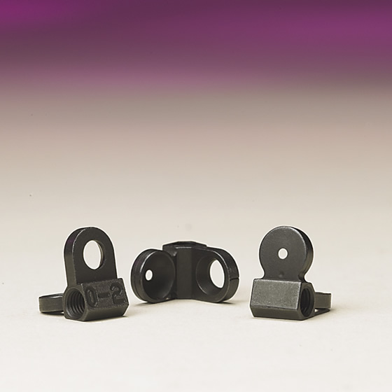
Courtesy of Metal Powder Industries Federation
Megamet Solid Metals makes this nickel-steel rear sight for sporting and military rifles via MIM. Secondary operations are tapping and nitride finishing.
The reasons for coining are several. “If they don’t use the correct powder shape, you are going to have problems with slumping,” Ryer’s Peterson said. He added that “there are three types of metal powder—spherical, rounded and irregular. Perfectly round spheres of different sizes are hard to interlock or stack, while various shapes of rounded forms are easier to interlock. In addition, irregular, jagged shapes stack well, but they conglomerate easily, which can cause flow issues. Therefore, you have to use the powder that gives you the best overall shape retention but still flows well. This is usually the rounded powder.”
The debinding process can also change the part shape, requiring coining. Water, solvent, supercritical fluid, thermal and catalytic extractions are all methods that can be used in debinding. Water, solvent and supercritical fluid have little effect on slumping at temperatures at or below 125° F (52° C) during the debinding cycle. Thermal debinding temperatures are up to 527° F (275° C) for several hours and catalytic debinding temperatures up to 248° F (120° C) for a few hours. In comparison, MIM materials typically mold between 330° F to 390° F (166° C to 199° C), so parts during thermal and catalytic debinding are above or just below the melt temperature of the material.
Finally, some part shapes will experience fatigue and start to bend during sintering because of the part configuration. “Some parts don’t have a good place to rest [such as a flat surface] during the sintering process,” Peterson said. “They don’t have a shape to prevent slumping. When that happens, coining is required.”
Tooling Techniques
Engineers don’t design a part for the green state and hope it shrinks to the size they want. They design it in CAD as a finished part and the toolmaker scales up the part.
As stated, dimensional tolerances of ±0.003 " to ±0.005 " (±0.076mm to ±0.127mm) per linear inch can be commonly held on MIM parts. To achieve those tolerances, the tooling must be held to tight tolerances as well. “At Megamet, we look for the tooling to take up no more than 25 percent of our tolerances,” Dionne said.
Courtesy of Metal Powder Industries Federation
A mechanical introducer device for minimally invasive surgery contains five 17‐4 PH stainless steel MIM parts. The net-shape parts require no machining.
Closer part tolerances—±0.001 " or less—are possible. “Many of our molds require us to hold a 10 percent tolerance,” Mold Craft’s Liddell said. “This is where the value of a well-built mold comes into play. All the cavities need to be the same—within 0.0001 " or 0.0002 "—to ensure a 1.33 Cpk or better.”
Tooling for MIM is similar to that for plastic-injection molding, but there are differences. The biggest difference is the shrink factor of 15 to 22 percent. “This means that a part that needs to finish at 1 " will be cut in the mold at 1.200 ",” Liddell said. “When features are at the micromold level, 20 percent shrink factor can be a game changer for mold manufacturability.”
The metal feedstock used in MIM is more abrasive than plastic, so the tools do wear faster. Typical MIM tools are made from D-2 steel. Moldmakers do not recommend any low-carbide steel for MIM tooling.
Another difference between plastic and MIM tooling is the gating, where the feedstock enters the mold cavity. “The gating is very specific to the MIM process,” Dionne said. “We need a substantial gate to make sure we are able to fill the part with the lowest number of voids and flow lines with maximum density.”
Also, it is critical to keep the parting line edges sharp because MIM feedstock flashes, or escapes, more easily than most plastics, noted Mold Craft’s Liddell. Feedstocks for MIM typically flash somewhere between 0.0001 " (0.0025mm) and 0.0003 " (0.0076mm), where plastics are generally 0.0005 " (0.0127mm) to 0.001 " (0.025mm). “We’re able to preserve these edges using high-quality electrode materials and very fine EDM channels,” he said.
MIM tooling is commonly polished so it can produce high-quality parts. “Typically, an EDM finish has a fine texture, and if it is on the side walls of the part, it can make it more difficult to eject the part,” Dionne said. “Toolmakers often draw polish, which is in the direction of ejection, to allow for smooth ejection.”
Tooling is a big part of the cost when performing MIM. Without the proper knowledge, the tooling can go through several intermediate stages before the final one is achieved. “If something goes wrong, perhaps calculating the shrink rate incorrectly, you may have several iterations of tooling,” MPIF’s Adams said. “But good MIM part designers and moldmakers utilize design modeling and analysis to greatly reduce error. The technology has advanced from an art to a science over the past decade.” CTE
Contributors
Megamet Solid Metals Inc.
(314) 739-4499
www.megamet.com
Metal Injection Molding Association
(609) 452-7700
www.mimaweb.org
Mold Craft Inc.
(651) 426-3216
www.mold-craft.com
Ryer Inc.
(951) 296-2203
www.ryerinc.com
Related Glossary Terms
- abrasive
abrasive
Substance used for grinding, honing, lapping, superfinishing and polishing. Examples include garnet, emery, corundum, silicon carbide, cubic boron nitride and diamond in various grit sizes.
- computer numerical control ( CNC)
computer numerical control ( CNC)
Microprocessor-based controller dedicated to a machine tool that permits the creation or modification of parts. Programmed numerical control activates the machine’s servos and spindle drives and controls the various machining operations. See DNC, direct numerical control; NC, numerical control.
- computer-aided design ( CAD)
computer-aided design ( CAD)
Product-design functions performed with the help of computers and special software.
- electrical-discharge machining ( EDM)
electrical-discharge machining ( EDM)
Process that vaporizes conductive materials by controlled application of pulsed electrical current that flows between a workpiece and electrode (tool) in a dielectric fluid. Permits machining shapes to tight accuracies without the internal stresses conventional machining often generates. Useful in diemaking.
- fatigue
fatigue
Phenomenon leading to fracture under repeated or fluctuating stresses having a maximum value less than the tensile strength of the material. Fatigue fractures are progressive, beginning as minute cracks that grow under the action of the fluctuating stress.
- fixture
fixture
Device, often made in-house, that holds a specific workpiece. See jig; modular fixturing.
- flash
flash
Thin web or film of metal on a casting that occurs at die partings and around air vents and movable cores. This excess metal is due to necessary working and operating clearances in a die. Flash also is the excess material squeezed out of the cavity as a compression mold closes or as pressure is applied to the cavity.
- flat ( screw flat)
flat ( screw flat)
Flat surface machined into the shank of a cutting tool for enhanced holding of the tool.
- grinding
grinding
Machining operation in which material is removed from the workpiece by a powered abrasive wheel, stone, belt, paste, sheet, compound, slurry, etc. Takes various forms: surface grinding (creates flat and/or squared surfaces); cylindrical grinding (for external cylindrical and tapered shapes, fillets, undercuts, etc.); centerless grinding; chamfering; thread and form grinding; tool and cutter grinding; offhand grinding; lapping and polishing (grinding with extremely fine grits to create ultrasmooth surfaces); honing; and disc grinding.
- lapping compound( powder)
lapping compound( powder)
Light, abrasive material used for finishing a surface.
- lathe
lathe
Turning machine capable of sawing, milling, grinding, gear-cutting, drilling, reaming, boring, threading, facing, chamfering, grooving, knurling, spinning, parting, necking, taper-cutting, and cam- and eccentric-cutting, as well as step- and straight-turning. Comes in a variety of forms, ranging from manual to semiautomatic to fully automatic, with major types being engine lathes, turning and contouring lathes, turret lathes and numerical-control lathes. The engine lathe consists of a headstock and spindle, tailstock, bed, carriage (complete with apron) and cross slides. Features include gear- (speed) and feed-selector levers, toolpost, compound rest, lead screw and reversing lead screw, threading dial and rapid-traverse lever. Special lathe types include through-the-spindle, camshaft and crankshaft, brake drum and rotor, spinning and gun-barrel machines. Toolroom and bench lathes are used for precision work; the former for tool-and-die work and similar tasks, the latter for small workpieces (instruments, watches), normally without a power feed. Models are typically designated according to their “swing,” or the largest-diameter workpiece that can be rotated; bed length, or the distance between centers; and horsepower generated. See turning machine.
- parting
parting
When used in lathe or screw-machine operations, this process separates a completed part from chuck-held or collet-fed stock by means of a very narrow, flat-end cutting, or parting, tool.
- sintering
sintering
Bonding of adjacent surfaces in a mass of particles by molecular or atomic attraction on heating at high temperatures below the melting temperature of any constituent in the material. Sintering strengthens and increases the density of a powder mass and recrystallizes powder metals.
- tapping
tapping
Machining operation in which a tap, with teeth on its periphery, cuts internal threads in a predrilled hole having a smaller diameter than the tap diameter. Threads are formed by a combined rotary and axial-relative motion between tap and workpiece. See tap.
- tolerance
tolerance
Minimum and maximum amount a workpiece dimension is allowed to vary from a set standard and still be acceptable.