Raising the CNC Technology Bar
Raising the CNC Technology Bar
Overview of the new machine tool technologies introduced at IMTS 2000. Among them are linear motors for axes travels, ballscrew chillers, a new way to lubricate linear guideways and controlling machining processes via the Internet.
Machine builders set to roll out new CNC technologies at IMTS.
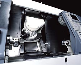
The addition of Y- and B-axis capability to a turning center creates a more complete multitasking machine tool.
Machine tool builders exhibiting at IMTS 2000 plan to display some major advancements in CNC technology. While many are tight-lipped about the details of specific models, CUTTING TOOL ENGINEERING was able to review some of the individual technology developments that will make this show a must-attend event.
The Need for Speed
Linear motors for driving axis-travel will debut in many new CNC machine tool models. Mazak Corp., Mori-Seiki, Okuma America Corp. and Cincinnati Machine are among a host of builders that plan to introduce machines with feed rates in the range of 2,400 ipm and rapids that are nearly twice that speed, thanks to linear-motor technology.
One such machine, Cincinnati Machine's Hyper-Mach, will be unveiled as a prototype, according to company product manager Randy Von Moll. It is the outgrowth of a collaboration among major aerospace players Boeing Aircraft Corp., McDonnell Douglas Corp. (before the merger with Boeing), the United Technologies Research Center, Sikorsky Aircraft Corp. and the U.S. Air Force.
"We set goals of what part requirements and machining parameters would be needed in the next 10 to 20 years," said Von Moll. "Then we decided what technology would be needed to meet those goals. One of the first elements we decided to utilize was linear-motor technology."
According to Von Moll, the prototype will accelerate and change direction at 2Gs, or nearly 800 in./sec.2. The 5-axis toolchanger. See toolchanger/" data-glossary-id="142091" data-glossary-teaser="Mechanism typically included in a machining center that, on the appropriate command, removes one cutting tool from the spindle nose and replaces it with another. The changer restor…" title="Mechanism typically included in a machining center that, on the appropriate command, removes one cutting tool from the spindle nose and replaces it with another. The changer restor…" aria-label="Glossary: automatic toolchanger">automatic toolchanger." title="CNC machine tool capable of drilling, reaming, tapping, milling and boring. Normally comes with an automatic toolchanger. See automatic toolchanger." aria-label="Glossary: machining center">machining center is designed to feed at 2,400 ipm and rapid at 4,000 ipm during routine production.
"A directional change of 2,400 ipm to zero, and then back to 2,400 ipm, will appear instantaneous to the naked eye," said Von Moll.
Peel Out
Michael Backman is the director of linear-motor business development at Anorad Corp. The Hauppauge, N.Y., manufacturer is supplying its LFB-series linear motor to drive the axis motion of the Hyper-Mach. Backman said that, conceptually, a linear motor can be thought of as a standard permanent-magnet, rotary-style motor slit axially to the center and then peeled back and laid flat (Figure 1).
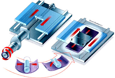
Figure 1. The linear motor is functionally the same as a rotary motor. Conceptually slice the motor from the OD to its core, then peel it back and lay it out flat.
The LFB linear motor consists of a copper winding surrounding an iron core located in the machine table. This is opposed by neodymium permanent magnets located in a channel cast into the machine base. (Neodymium is a rare-earth metallic element.)
A linear guide system creates and maintains a 0.5mm air gap between the permanent magnets and the electromagnetic core, and also provides stiffness to the overall system. The magnetic attraction between the permanent magnets and the core creates the powered movement of the machine table.
According to Backman, the major advantage of a linear motor is that it eliminates the inefficiency and mechanical variance caused by the ballscrew assembly system used in most of today's CNCs. "By comparison, the ballscrew/servo system is very inefficient," said Backman.
The ballscrew method of motion in a typical machine tool can be thought as a motor connected to a gearbox. While there are torque advantages, the efficiency of energy transfer from the motor to the load—in this case the machine table—drops dramatically, said Backman.
The servomotor must overcome the inertia of the ballscrew, an inertia that increases with its length. This inertia must be overcome to put the table in motion, and to then stop it quickly and accurately. Remember that inertia works both ways: A body at rest tends to stay at rest, and a body in motion tends to stay in motion.
"Many times," said Backman, "the total inertia of the mechanical ballscrew system is greater than the load (machine table, fixture and part) it is supposed to carry. This means that when the load is accelerated along the axis, the majority of the servomotor's initial torque is being used just to accelerate the ballscrew assembly."
In a linear-motor system, there is very little inertia between the motor and the load. Therefore, machining performance is far more accurate and easier to maintain than with a mechanical ballscrew system.
"There are no parts that will wear, experience thermal growth or create backlash," said Backman. "There is no torsional strength of the ballscrew to be concerned with, and no stiffness issues with the axial or thrust bearings, or the gearbox."
Because the motor directly drives the load, all of these mechanical issues are removed from the motion equation. However, Backman cautioned that there are concerns that must be addressed with the linear-motor approach. Low-speed torque is probably the biggest issue. Readers may recall that the need for higher speed, acceleration, C-axis positioning accuracy and better surface finishes drove many builders to replace the belt-pulley-motor method of driving a lathe spindle with an integrated approach.
The spindle became the rotor of an AC motor. The belts and pulleys were replaced by copper windings surrounding a rotor that allowed direct drive (Figure 2). But with virtually no mechanical advantage between the motor and the spindle, users quickly discovered that there was very little torque at lower spindle (motor) speeds.
Figure 2. On the left, the old belt-and-pulley design. On the right, the induction motor that replaced the belt-and-pulley system. The spindle was integrated in the motor's rotor to increase speed, response and accuracy.
The system of gears or pulleys between the motor and the load allows the motor to run fast enough to create the needed rotational torque. This "less-efficient" system actually helps to create high torque at a low rpm. But without it, common machining operations, such as making power cuts and tapping, become difficult. The only answer is a more powerful motor, which increases both the cost and size of the spindle.
Conceptually, if you were to take an integral-spindle motor, slit it axially to the center and then peel it back, you would have a linear motor—complete with no low-speed torque. This characteristic may be one reason that the first linear-motor machines are being targeted at aerospace and moldmaking applications, where fast feed rates and small DOCs are needed.
Until there are further performance developments in linear-motor technology, Backman said that builders might be able to offer a combination approach. Some axes could be powered by a traditional ballscrew system, such as the Z-axis for low-speed drilling and tapping, while linear motors powered the other axes.
Cool It
Many high-speed machining centers at IMTS 2000 will feature ways to keep the machine tool's temperature under control.
In ballscrew applications, once machine tool rapid rates exceed 1,200 ipm, the heat generated within the ballscrew must be evacuated to avoid thermal growth and the related drop in positioning accuracy, according to Mike Sess, process development engineer at Makino Inc., Mason, Ohio.
To combat ballscrew heat, Yusaf Venjara, chief engineer for the North American operations of Hitachi-Seiki USA, Itasca, Ill., said that a ballscrew chiller will soon become standard on all high-speed machining centers. A hollow core traverses the length of the ballscrew and is filled with recirculating oil that runs through a chiller. It is the same approach that continues to be popular in high-speed spindle designs.
According to Jason Calimlim, a Makino product specialist, an electronic chiller-control system monitors the temperature, keeping the ballscrew temperature the same as the machine casting to achieve maximum thermal stability during a machining operation.
And to keep the workpiece and cutting edge cool, Mark Mohr, vice-president of Yamazen Inc., Indianapolis,
said that high-speed spindles with high-pressure (1,000 psi minimum), through-spindle coolant will be much more prominent at this year's show. The high pressure helps minimize problems common to high-speed machining, including short tool life, accelerated tool wear and inadequate chip evacuation.
Another area of the machine tool that must avoid excess heat are linear guideways. Hitachi is applying a new approach to way lubrication called Eco-Eco (Figure 3). The linear guideway trucks are packed with a new lubricating resin developed by the bearing manufacturers.
Figure 3: Eco-Eco stands for economy and ecology. This self-contained lubrication method can eliminate the need for a central lube system on a CNC machine tool.
"There is no lube tank in the machine at all," explained Venjara, "because even the ballscrew itself is lubricated in this manner."
The new environmental standard, ISO 14000, will soon have most machine tool builders adopting this technology, according to Venjara. This self-contained, environmentally friendly system provides positive and reliable lubrication, along with the economic benefits of not having to purchase or dispose of lube oil.
Maximum Multitasking
The continued push to completely machine parts in a single setup will be in evidence at IMTS 2000. New lathe designs welcome B-axis to the machining party with the kind of power and capability that just might make 4- and 5-axis vertical and horizontal machining centers look downright clumsy by comparison.
Many of the new lathe designs will have full machining center capabilities, including an automatic toolchanger, akin to HMCs and VMCs, said Michael Cassell, director of technical resources at Okuma America Corp., Charlotte, N.C. He also said that more machine automation is on the way, a response to the shrinking skilled-labor pool.
George Yamane, marketing manager at Mazak Corp., Florence, Ky., said that the new breed of multitask machine features a spindle mounted so that it can be rotated to allow machining in the B-axis. This increases machining capability and reduces the number of toolholders needed for turning operations. Unlike a turret, a milling spindle that can be rotationally positioned "will not need the separate left- and right-hand toolholders required by a turret-style lathe," said Yamane.
So, are these new multitask CNCs called turning centers or milling centers? Venjara said that the difference between turning and vertical milling will be a gray area at IMTS 2000.
Old Dog, Better Trick
Some older models of CNC machine tools at IMTS 2000 will have gotten a power and capacity boost from new, rare-earth, permanent-magnet rotary motors. These motors replace the induction spindle motors used in live-tool lathes.
According to Yamane, there are several advantages to the new design, compared to induction motors. First, more power is available. While both motors were rated at 10 hp and a maximum speed of 6,000 rpm, the new integrated-spindle motor with rare-earth permanent magnets is capable of producing 118 ft.-lbs. of peak torque. The induction motor produces a peak torque of only 70 ft.-lbs.
The second advantage is the control of heat and the negative effects thermal growth has on machining accuracy. The permanent-magnet motors are easily cooled with air, eliminating the need for a spindle chiller.
The third advantage is size. Permanent magnets take up less physical space than comparable induction windings. This means that the size of the spindle bore can be increased without increasing the overall size of the spindle cartridge. An integrated, induction-style spindle that previously had a 52mm through-hole, for example, now can have a 61mm through-hole, which gives the user greater bar capacity.
This more powerful motor design will reportedly find its way into machine turrets as well, increasing the available power for live-tool machining.
YourCNC.com?
"It takes a lot of [machine tool and development] money to reduce a machine cycle time from three minutes to 30 seconds," said Yamane.
But if reducing the amount of time it takes a machine to produce a part doesn't allow the customer to deliver that part more quickly, the payback can be significantly less.
As a result, Yamane said that machine tool builders are now addressing the need for their machines to provide real-time information to all key functions in a manufacturing organization, supporting a coordinated effort to develop the most productive total process possible—from order entry to delivery.
Cassell said that it will soon be commonplace for a company's machine tools to be networked into its manufacturing communication and control process. If the machine tool experiences a problem, a signal will be sent to a designated party via the Internet, allowing action to be taken immediately, he said.
This automatic accumulation and real-time dissemination of machining information from the CNC via the Internet represents the new frontier of manufacturing productivity. But a benefit that all customers can enjoy right now is improved service and support via the Internet.
At IMTS, most builders will demonstrate some form of online network support for their machine tools. As an example, the new PC-based machines Cincinnati Machine plans to introduce will allow a customer's programming, operation and maintenance personnel to have direct, bidirectional audio, video and control diagnostic communications with Cincinnati's national support center.
According to Bill Horwath, Cincinnati Machine's sales and marketing manager, the customer can purchase an optional software bundle, modem, Web camera and an audio headset. No Internet service provider is required—just a standard telephone line. The software will let the customer participate in a true interactive problem-solving session about a machine or application.
Horwath believes that the interactive nature of the communication can shorten downtime dramatically. "And [interactive communication] naturally provides some virtual training at the same time," he said.
A Cincinnati Machine support specialist not only sees the program provided by the machine control, but the Web camera can display the part setup on the machine table. On the maintenance side, the service engineer can actually see the mechanical problem a customer is having. This eliminates the misdiagnoses that can occur when the customer has to describe the problem over the phone or fax a rough sketch illustrating the problem.
Another advantage to this approach, said Horwath, is the availability of future software upgrades for a builder's control. "[A builder] can download the software, install it and check it directly from a central office," he said.
Open Up
Open architecture for machine tool communication will take a giant step forward at IMTS. Venjara stated that all of the Hitachi-Seiki machine tools at the show will feature an open-architecture connection called a Universal User Port, which links a machine's CNC operating software to the Internet.
At IMTS 2000, some of Hitachi-Seiki's "Web-enabled" machines will demonstrate the system's remote-diagnostic capability, exchanging information at 10MB per second.
Notably, Hitachi-Seiki is taking its Internet concept one step further by making its operating system available for the development of third-party applications. The company is providing the actual source code of its HS-MOS operating system so that software developers, or a customer, can write diagnostic and reporting software using Visual Basic or C-language programming.
Venjara said that this open approach will allow customers to build or buy a software reporting system that more effectively meets the particular needs of their businesses.
Venjara said today's CNC and Internet developments can be compared to the advent of television back in the 1950s. "We have the television tower in the form of the Internet, and the TV in the form of the CNC operating system," he said. "The only thing left is the development of programs." In this case, the program is a piece of application software instead of a sitcom.
Venjara added that machine tool builders are very close to devising a way for a PDA (personal digital assistant) device, such as the Palm Pilot, to be used for real-time, wireless Internet access to a shop's CNC machines. When available, a user will be able to check production output, help solve a problem or simply e-mail the CNC operator—from anywhere in the world.
Maybe even from an exhibit hall at IMTS 2000.