RFID tagging for toolholders
RFID tagging for toolholders
The tagging applications for radio frequency identification (RFID) are vast, including pets, property—and even people. Recently, Micro-Mechanics Inc., a Morgan Hill, Calif., machine shop, worked with process control equipment provider Caron Engineering Inc., Wells, Maine, to implement an RFID tagging system on its Okuma LB series CNC lathe.
The tagging applications for radio frequency identification (RFID) are vast, including pets, property—and even people. Recently, Micro-Mechanics Inc., a Morgan Hill, Calif., machine shop, worked with process control equipment provider Caron Engineering Inc., Wells, Maine, to implement an RFID tagging system on its Okuma LB series CNC lathe.

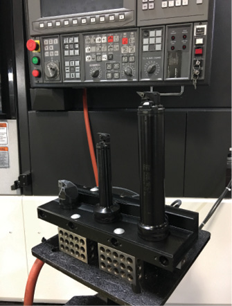
The RFID read-station on Micro-Mechanics' Okuma lathe transfers tool offset and usage data directly to the machine control. Image courtesy Micro-Mechanics.
Micro-Mechanics is no newcomer to RFID. Company president Chris Borch and his team began "reinventing" the shop 5 years ago after installing several Makino horizontal machining cells with Makino's Modular Machining Complex (MMC2) technology and integrating them with RFID readers. Since then, the shop has rolled the technology out to every part of the shop. "Nothing hits the floor unless it's been preset, tagged and simulated ahead of time," Borch said.
Its latest addition is a Tool Connect system from Caron Engineering, which reportedly is a simple, cost-effective way to automate the transfer of data from a presetter to a machine control. The system at Micro-Mechanics uses an RFID chip epoxied into Sandvik Coromant Capto quick-change toolholders.
Micro-Mechanics presets each tool offline and writes the X-axis offset, or tool diameter, for milling cutters and tool length (Z-axis offset) to the chip with the push of a button. Once at the machine, the tools are individually loaded into a cradle, which reads the offset and other tool data, such as the expected tool life, and sends it to the control. The operator then places the tool in the appropriate turret position before moving to the next tool.
Ryan Hegman, national sales manager at Caron Engineering, emphasized the high level of accuracy Tool Connect provides. "The data comes directly from the presetter," he said. "This not only eliminates the chance of operator error, but significantly reduces setup time. Another very important point is the ability to automatically keep track of tool life. Because the system updates each tool with usage data upon removal from the machine, maximum utilization of cutting tools is assured."
Borch agreed. He said the machine uptime percentage at Micro-Mechanics is in the high 90s, and setup time went from several hours to 5 minutes. This is quite an achievement when you consider that Micro-Mechanics is a high-mix, low-volume shop that makes parts for the aerospace, semiconductor and medical industries. "If suppliers are interested in developing a controlled machining process, then one of the first and most important steps is RFID tool management," Borch said. "The technology itself is quite simple—you're just reading and writing data. But it's a very important piece of a complete digital manufacturing solution."


