Scalable CAM technology tips
Scalable CAM technology tips
This month's Get With The Program column in Cutting Tool Engineering magazine considers the advantages of scalable CAM software.
Job shop owners should avoid getting boxed in with basic CAM software that seems adequate for their current needs but does not allow them to exploit more advanced capabilities as they grow. This kind of CAM software costs less initially, but a shop will have to install a more comprehensive package and train its workers as the shop's requirements multiply. A better alternative is a scalable CAM package that allows users to upgrade as needed so the business can keep growing smoothly.
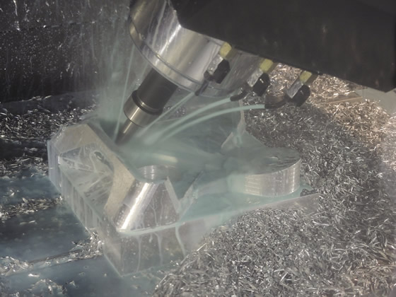
When cutting tools with advanced designs are paired with the right toolpaths and coolant, they can pay for themselves many times over in terms of increased productivity. All images courtesy CNC Software.
The following are some methods small shops have employed to strengthen their businesses with scalable CAM software.
■ Customized posts are needed to get a CNC to behave as expected based on the code generated by CAM software. These posts allow for higher operating efficiencies as more CNC equipment is installed, because each machine will behave consistently.
■ Although more expensive, carbide cutting tools with advanced designs cut faster and last longer than conventional cutting tools. When paired with the right toolpaths and coolant, they can pay for themselves many times over via increased productivity.
■ Advanced cutting algorithms, such as those in Mastercam's Dynamic Motion technology, continually adjust feeds, speeds, entries and exits based on the program's knowledge of material conditions ahead of the tool. This provides a consistently smooth tool motion that maximizes allowable chip loads without excessively wearing or breaking a tool.
■ Shops that employ conventional CNC programming can often improve the profitability of repeat jobs by rewriting the programs using material-aware toolpaths. Typically, the cost associated with rewriting the program is recovered through increased machining productivity.
■ CNC equipment can run during long shifts while continuously operating at the highest allowable chip loads. With the trend toward short production runs, too much time can be lost stepping through a program to make sure it is safe. Shops must be have the confidence to post the program and go full tilt. This is accomplished by simulating everythingthat has been written into the program at every stage, consuming a few seconds per stage.
■ Understanding the best feed rates and speeds to use with specific tools for producing various part geometries is proprietary knowledge that should be available to all shop workers. It should not have to be recalculated and reentered into the CNC program every time a similar job arrives. Tool libraries capture this information and automatically enter it into subsequent programs, saving time while ensuring all programmers are using proven settings.
■ Similarly, as a shop grows, the knowledge that was once resident in the head of the owner or lead programmer must be consistently shared with those who need it. Marking drawings of setups is the typical approach. Small startups have a unique opportunity to communicate consistency at the outset by developing setup sheets that concisely convey—in computer-generated images and words—exactly how a part should be set up and run. This is far easier to do when a shop has one or two machines and employs just a few people than later, when multiple approaches to conveying part setup information must be sorted out.
Simulation enables a shop to be confident that it can post a program and go full tilt.
■ When making families of parts, one good manufacturing program can serve as a template for other parts in the same family. This makes it possible to generate manufacturing programs in minutes by dragging and dropping toolpaths and other information from the master program template.
■ When quoting complex work, it is often beneficial to obtain a seat for the CAD program that was used to design the part. This makes it possible, for example, to evaluate the CAD model to ensure it is complete, give design-for-manufacturing feedback to the customer and create workholding fixtures based on mirror images of critical part features. This helps reduce lead times and reduce the time burden on the customer if the shop must repeatedly ask for clarifications of design intent.
■ If a shop works with customers on prototyping, having a CAM programming solution embedded in the design software can eliminate the time spent reviewing and reconciling changes made in either the CAD model or CAM software. For example, Mastercam for SolidWorks has been adopted by numerous shops that must live simultaneously in the design and manufacturing realms. It is fully associative, so changes made to the model in the design or CAM environment are automatically reconciled. This approach saves time and money, reduces errors and shortens lead time for prototypes.
■ Advanced CAM software packages have myriad capabilities. Two examples are oscillating toolpaths that reduce tool wear during trimming, and the ability to compare an STL file generated in CAM to the CAD model and inspect the part before making it. Most part manufactuers don't have the time to browse through a CAM package's capabilities and determine which ones could offer advantages. However, if a shop has a good working relationship with its CAM software reseller, the reseller should be able to point out beneficial capabilities based on his understanding of the shop's manufacturing challenges.
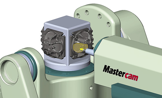
■ As component complexity increases, 4- and 5-axis machine tools must achieve tight tolerances. In addition to upgrading CAM software so it supports multiaxis programming, almost all of the other moves mentioned here make multiaxis manufacturing more effective. CTE


