A Simple Groove
A Simple Groove
This article discusses the trend among insert makers to consolidate chipbreaker designs and carbide grades. The result is the three-chipbreaker/three-grade matrix many insert makers have adopted in some form. The evolution of the chip-forming groove is also traced, and an ANSI proposal for a grade identification system is described.
Insert makers are consolidating and standardizing their once bewildering array of chipgroove designs for carbide turning inserts.
The chipgroove, once a simple feature on the side of a carbide turning insert, has evolved into a highly specialized bit of tool geometry. Nearly every niche application, it seems, has its own design. Users hoping to find the right geometry for their jobs have to pick through a confusing assortment of patterns with varying angles, widths, peaks, and valleys.
Recently, toolmakers have begun to reverse this trend toward increasing diversity and specialization. They are turning to a new standardized system that offers users a choice of just three grooves and three carbide grades.
In the Beginning
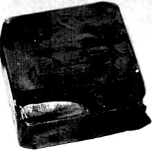
Figure 1: Craters like this, which are the result of wear on flat-top inserts, were the inspiration for the original chipgroove.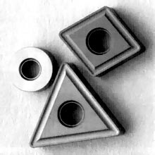
Figure 2: The basic chipgroove for breaking chips is simply a channel running parallel to the cutting edge.
This brings the development of the chipgroove nearly full circle. At first, insert manufacturers offered just one basic chipgroove configuration. This design was patterned after the crater that became worn into a flat-top insert during use (Figure 1). Insert designers had seen how this depression in the side of the insert could break the long, stringy chips that turning produced into a number of small chips shaped like the letter "C" or the number "9."
Machinists found that chips were safer and easier to handle broken into small pieces. Long chips get snarled together. The tangled ball of metal these intertwined strands form is known as a bird nest. A nest caught in a chuck can be pulled, spun, or twisted uncontrollably, marring the workpiece or injuring the operator in the process. A nest that finds its way into the gaging equipment can shut down an entire operation. Long chips that do make it into the chip conveyor take up so much space that they can jam the machine's automatic chip-handling equipment.
A simple depression in the face of the insert was all that was needed to break these long strands into manageable bits. It was easy to add this shape to the basic carbide-insert design. Manufacturers simply pressed the groove into the insert while they were compacting the carbide and cobalt powders together. This basic chipgroove configuration was the universal choice of users and manufacturers for many years (Figure 2). But when manufacturers discovered that some negative-rake inserts with chipgrooves would cut as if they had a positive rake, they began to see uses for the chipgroove that went beyond its original chip-breaking function.
Before chipgrooves were introduced, manufacturers created positive-rake tools by tilting the tool backward 10° and grinding a clearance on the insert's flank. But with this clearance ground into the flank, only the insert's top cutting edge could be used. For applications where the added support of a solid bottom wasn't needed, this was a waste of the insert's geometry. Manufacturers found they could achieve the same positive cutting action without slanting the tool or grinding flank relief if they eliminated the land between the chipgroove and the cutting edge or created a land that slanted back. The chipgroove's geometry might create a 20° slope tilting back away from the cutting edge on the insert's face. When this insert is installed in a holder with a 5° negative tilt, it creates an effective positive rake of 15°.
This solution gave users the benefits of both positive- and negative-rake cutting. With a positive geometry at the cutting edge, the insert requires less energy to separate the chip from the workpiece and direct the chip over the insert face. A negative-rake insert pushes and compresses material ahead of it until the chip it forms breaks free of the workpiece. This plowing action generates more heat and subjects the insert to greater forces.
A positive-rake insert is more likely to break than a negative-rake insert, however. The acute angle formed between the face and flank of a positive-rake insert leaves much of the tip unsupported directly beneath the area where cutting forces are concentrated. In a negative-rake tool, the cutting edge is supported by the toolholder as well as the body of the insert (Figure 3).
Figure 3: A positive-rake insert has much less support than a negative-rake insert beneath the area where stress is the greatest.
A negative-rake insert with a chipgroove retains this support. But at the cutting edge, it has enough of a positive rake to promote freer cutting. The dual advantages of this type of insert have made it the preferred choice of users who want a positive-cutting tool.
Groove Proliferation
Chipgrooves weren't just for breaking chips anymore. Having expanded the chipgroove's role, insert manufacturers began to experiment with different geometries, each designed for a narrow range of applications. They enlisted the aid of CAD/CAM systems to tweak their designs. With the computer's help, they created a proliferation of chipgrooves. They experimented with grooves that produced positive angles ranging from 5° to 30° at the cutting edge. They devised varying patterns of curves and ridges to direct chips away from the workpiece. They tried different land widths and different degrees of support under the cutting edge. And they offered chipgrooves designed for specific workpiece materials.
Some companies' catalogs listed as many as 40 different grooves. The trend left users confused. Unless a chipgroove had been designed for their specific purpose, they had to determine which objectives were their highest priority and then search through a selection of grooves for the design that would achieve that particular combination of objectives.
A Simpler Solution
In the late 1980s, insert manufacturers began to consolidate their chipgroove designs to simplify the selection process. With modifications, their chipgrooves' application ranges were broadened, and lines of highly specialized inserts were dropped in favor of designs with more general applicability.
This reduction in the number of chipgrooves has benefited users and manufacturers alike. With fewer designs to choose from, users can find the right design for their applications more easily. Shops that do not have the staff to evaluate a large variety of chipgroove geometries find this especially beneficial. Generalized inserts also cost less than specialized inserts. Manufacturers can mass produce the generalized inserts because each is designed for a broad segment of the market. Users who switch to generalized inserts will not need to inventory as many, because one type of insert will suffice for a number of applications.
Figure 4: The three-groove/three-grade system simplifies carbide turning insert selection.
At the same time manufacturers have been reducing the number of chipgrooves they offer, they've been expanding the application ranges of their coated-carbide grades. The result has been the development of a three-groove/three-grade system that covers nearly all applications. Figure 4 shows how the three grooves and three grades typically offered by an insert manufacturer can be combined to create inserts with specific characteristics. Chipgrooves with a 15½ positive effective rake can be found in Column 1 of the chart. Because of their higher rake angle, these inserts cut with the most efficiency. They also are the most prone to breakage. Column 2 features general-purpose inserts with a 5° effective positive rake. Column 3 inserts, with their negative rake, are for tougher cuts. Rows A to C progress through increasingly tougher carbide grades.
To use the three-groove/three-grade system, a machinist would start with the insert his supplier recommends for the workpiece material, machining parameters, and tolerances with which he will be working. If this insert produces a satisfactory cut and the tool does not fail prematurely, the machinist can continue using the recommended insert. But if edge chipping causes the insert to fail, the machinist can consult the chart to determine what chipgroove/grade combination might offer better performance.
If the insert is breaking in the chipgroove, the machinist might try an insert with a tougher groove. If, for example, he began with insert B1, which is a P-30 grade carbide with a 15° positive groove, he might move to insert B2, with a 5° positive groove. If the insert failed because its corner broke off, the machinist might try insert C2. The P-40-grade carbide with a 5° positive rake insert offers a tougher grade as well as a tougher groove. If back-pressure on the insert's plateau seems to be the problem, changing to a C1 insert, which is made with a tougher P-40-grade carbide and a 15° positive rake, might be the solution.
Figure 5: ANSI's proposed classification system divides inserts into six categories based on the DOC and feed with which they are to be used.
A proposal developed by ANSI for adoption by ISO would give users additional guidance. The proposal outlines an identification system that groups chipgrooves into six categories according to the DOC and feed with which they are to be used. The classifications, designated A through F, can be used by the insert manufacturers to indicate their products' primary uses (Figure 5).
Even though manufacturers are consolidating and standardizing their inserts, there still will be those applications that call for specialized designs. An application run on an old or poorly maintained machine, for instance, will require an insert that can handle heavy vibration. Even a C3 insert from the three-groove/three-grade scale will lack the toughness for such a job. A single-sided insert should work, however. The design's flat bottom offers the support the cutting edge needs. In the same way, a double-sided insert with lands ground to the same height as the insert's plateau will work. Because the cutting edge on the back side of the insert rests against the toolholder's pocket, it offers the same support as the back of a single-sided insert. This is a special design, however, that won't be found on the standard three-groove/three-grade scale.
Manufacturers also are consolidating their chipgroove designs for milling inserts. Although milling chipgrooves do not have to break chips, they are used to reduce cutting forces and direct chips in much the same way as chipgrooves on turning inserts are used. Consequently, the three-groove/three-grade system applies to milling as well as to turning inserts.
It seems certain that manufacturers will continue their trend toward chipgroove consolidation. Future chipgroove designs will offer even broader application ranges, simplifying the selection process and user inventories even more.
About the Author
Roy Leverenz is director of engineering for Teledyne Advanced Materials—Cutting Tools, La Vergne, TN.