Smart design
Smart design
Design for manufacturability is catching on among the more sophisticated clients of machine shops.
The design for manufacturability process can help designers understand how their parts will actually be machined. The challenge for machine shops that offer DFM services is to convince their customers to use it.
DFM means designing a product, part or assembly so the piece is easy to manufacture and manufacturing costs are reduced compared to a non-DFM part design. DFM allows potential problems to be fixed in the design phase, which is the least expensive place to fix them.

Courtesy of Pro CNC
Paul Van Metre (left), president of Pro CNC, and Estimator Andrew Miller discuss a part designed by the shop via design for manufacturability.
DFM takes into account every aspect of a product's design and manufacturing, including the workpiece material, time to production, machining methods and overall cost. The machine shops interviewed for this article offer DFM design reviews for customers based on their manufacturing experience and software tools such as GeoMagic Design, Creo Elements/Pro, Autodesk AutoCAD, Autodesk Inventor, Dassault Systèmes' SolidWorks or Siemens' Solid Edge for DFM.
DFM is not a new process for CAD/CAM programmers and machinists. It has been around as long as CAD, but it is only starting to become popular as more sophisticated clients of machine shops learn the advantage of consulting with shops on the manufacturability of their designs to avoid costly changes later in the process.
"Our large customers utilize our [DFM processes] frequently," said Larry Harrison, vice president of engineering at EMC Precision Machining, a machining business with shops in Elyria, Ohio, and Sheridan, Ind. "We make sure we have contacts with their design and engineering departments so we can be on the front end of their designs." Smaller customers tend not to be as interested in the service, he added.
In addition to consulting with customers on part design, EMC uses DFM to develop, design and prototype some parts for customers. Harrison said: "At times, we even have their engineers come in so they can make changes while we're preparing to manufacture parts, especially on small- volume part runs. They can then make changes here or back at their office. Our key customers are always talking to us about the design of their new projects."
Like EMC, Cohagan Engineering Inc. offers DFM services. "Usually, the relationship starts with an initial conversation to nail down exactly what the client is looking for and the best material to work with. Then we create a few hand sketches, get approval and submit an initial CAD design," said Brent Cohagan, president of the West Palm Beach, Fla., shop. His company offers design review, design collaboration and turnkey part design, mostly for customers in the aerospace and military industries. "The whole time we're thinking in terms of DFM because we want to design and create it as economically and efficiently as possible. That can sometimes hurt us because they can then take our design and go to any other shop for production, but that's a risk you take hoping to get that larger run down the road."
After a customer approves the initial CAD design, the shop makes some minor changes. Then, the customer approves the prototype and production begins.
Cohagan and Traver Maselli, a vice president at the shop, perform the company's DFM consultations, which sometimes include a licensed professional engineer for verification. Certain customers, such as large corporate customers with large engineering staffs that design their own parts, do not usually ask for DFM services, but they will accept feedback if there is something they've overlooked. Usually, it's the single-designer CAD shops that ask for DFM services. Cohagan charges a flat rate of $60 an hour for its services, no matter if the time is spent in doing DFM, machining or performing other services.
EMC Precision's Harrison also does not charge anything beyond the normal hourly shop rate for DFM. "It's a marketing tool and a partnership with our customers," he said.
Cohagan said the way most of his customers come around to using DFM is by learning first-hand the advantage of eliminating errors during design rather than in production.
"Usually, someone sends you an RFQ, you quote them the number and they ask 'why does it cost $1,500?' " After Cohagan explains that applying DFM can help reduce manufacturing costs, the customer typically gets on board with the process. "We can get those design changes early on, which reduces the cost, and [the customer] can be brought into the design review process," he said.
Mars and Venus
One of the hurdles to overcome in getting part and product designers to utilize DFM is the lack of communication between designers and shop owners. Achieving common ground on how to design a product, determining the desired result and how to get there can cause frustration and missed opportunities on both sides.
"The younger folks coming into the industry as engineers and designers know only about the software and not about how the parts are produced," Cohagan said. "We call them software jockeys. They can draw the most awesome CAD designs, but when it comes to making the part, it's almost impossible for us to machine.
Courtesy of Cohagan Engineering
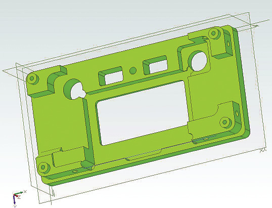
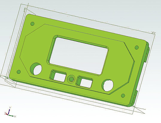
Cohagan Engineering designed and manufactured this aerospace bezel. The shop worked with the customer's engineering design team, applying DFM methods to reduce manufacturing costs and lead times. The old design consumed 80 minutes of machining time, for a cost of $88 each, while the new design (shown above and below) consumes just 25 minutes of machining time, for a cost of $33 each. Pictured is the front (above) and back (below) of the redesigned part, in which Cohagan Engineering removed sharp inside corners and all inside radii under 0.015" and changed a number of ±0.001" tolerance requirements to ±0.015", which were acceptable. In addition, the overall size was 0.015" to 0.020" larger than standard bar stock sizes. Cohagan Engineering reduced the part length and width to use standard stock and significantly reduced material costs.
"It's very difficult to find skilled workers who know both manufacturing processes and CAD software," he continued. "We try to find people that have backgrounds as hands-on mechanical engineers or machinists and also have CAD experience, rather than someone who is, say, SolidWorks-certified but lacks experience in manufacturing. Southern Florida has a large freelance CAD marketplace where people work out of their homes with one seat of software and a computer. When the CAD files they make get moved to us, we often ask, 'what is this?' " he said about the files, which often have multiple errors that makes manufacturing difficult or impossible.
Paul Van Metre, president of Pro CNC Inc., Bellingham, Wash., approaches this problem by taking on the role of DFM educator as well as CNC machinist. Before starting Pro CNC in 1997, Van Metre was a CAD manager for a bicycle manufacturer and a machinist for a motorcycle manufacturer. His shop mainly serves the aerospace industry.
For the last 3 years, Van Metre has produced a DFM e-newsletter, Pro Tips. To date, he has published 40 issues and his subscriber base has grown to nearly 1,500 engineers. The newsletter has led to the shop offering live classes on DFM for clients and prospective clients.
"With some of our customers, we go on-site and hold classes for half a day or so," Van Metre said. "We go through a bunch of topics, such as modeling techniques, tolerances, cutting tools, machine tools and what materials are the least costly. I explain our process on different part samples. You have to approach it in the right way to have it be well-received. I don't want to say engineers are a superproud bunch, but you have to understand where they're coming from. You don't want them saying, 'I'm a professional engineer, you're a machinist, how can you inform me about my designs?' "
Van Metre also holds DFM office hours on a weekly or biweekly basis at some customers' facilities to work with their engineers during the design, drafting and checking stages of a project. In addition to Van Metre, Pro CNC has a professional engineer who works on nearly every DFM project, and the company's manufacturing and programming engineers provide feedback on DFM projects as well.
"Many young engineers have never set foot in a machine shop," Van Metre said. "It seems crazy that they're designing machined parts, yet have no idea how CNC machining works, but that's how they're coming out of school these days. The beginning of our class goes back to basics—this is what a horizontal mill looks like, this is what a vertical mill looks like, these are the axes that move. We also look at how a machine tool can approach different sides of the part using different fixtures, the cost of different workholding approaches and the cutting tools we use. Most engineers are very receptive to learning this. The engineering program I went through was very hands-on and we designed and built parts. That's the foundation for how we started the company and how we still do it today."
Building DFM Relationships
The machine shops interviewed agreed that the success of DFM depends greatly on long-term client/shop relationships. Customers who feel comfortable communicating about design issues with machine shops often reap the rewards of DFM.
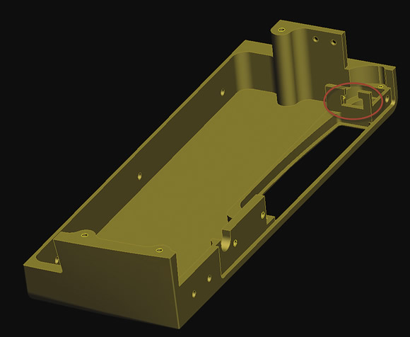
Courtesy of Pro CNC
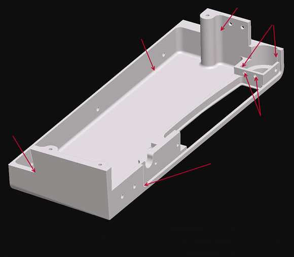
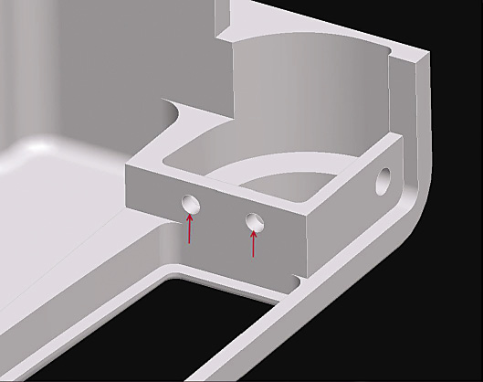
Pro CNC used DFM to redesign a group of four parts, including the one shown here, and make them significantly easier to machine. The original design (top) was changed to replace the two holes indicated in the close-up of a feature (above) with the circled T slot (below) so the part manufacturer could apply a standard cutting tool instead of a drill jig or a 90° angle head. In addition, Pro CNC optimized the radii indicated with arrows in the original design to increase machining speed. As a side benefit to changing the radii, the surface finish improved.
"It's been great for us and elevates us beyond a supplier to a partner with customers," Van Metre said. "There is enormous cost pressure everywhere in the industry. For example, Boeing is trying to cut 15 percent out of every supplier part. Most manufacturers and job shops don't even have a 15 percent margin to begin with. The only way to achieve price reduction is to use DFM to make the part less costly to produce."
Sue Jerovsek, product manager at Baker Engineering, understands relationships are key to making DFM work. The Nunica, Mich.-based CNC parts manufacturer specializes in high-performance engine parts and uses DFM with only a handful of clients. Many customers don't know about DFM or may be reluctant to use it. However, customers that do are seeing cost savings and bringing more work to the shop as a result.
"Our experience has shown that DFM success is often relationship-based," Jerovsek said. "Customers with whom we've created good working relationships are the most open to DFM dialogue. For parts that we make for our 'internal' customers (other departments in the shop), we build design reviews for DFM into the process before parts are released for production."
Real Savings
The cost savings from using DFM are turning heads with long-term customers that the shop knows well and who are comfortable with DFM. Jerovsek gave the example of one Baker Engineering customer that ordered threaded jack screws for a part. The customer's material specification did not allow the jack screws to be made from threaded rod, so they would have required machining the threads. Baker was able to save 30 percent of that cost by explaining how switching from the original material to threaded rod would save hours of machining time. Once the customer realized the costs savings of using threaded rod, it changed the spec.
EMC's Harrison told a similar story about a customer who had designed a complex stainless steel part. Through communication about the manufacturability of that product, EMC was able to decrease machining time 50 percent by changing the work material from stainless to easier-to-machine coated brass.
Pro CNC's Van Metre cited a DFM success story that involved a batch of four parts, which were part of a larger production order. When the customer could not achieve the quoted cost for the relatively high-volume parts, Pro CNC began working on a DFM solution. One of the parts, shown on pages 70 and 71 in before and after versions, is an example of the package of changes made via DFM that reduced production costs by 20 percent for the part batch.
In the example shown, Pro CNC increased the radii of the internal pockets. This allowed the replacement of a 0.25 "-dia. endmill with a 0.5 "-dia. one with a 3:1 length-to-diameter ratio, and also made the radius of the internal pockets about 10 percent larger than the cutter radius. This approach imparted a finer surface finish, of at least 20µin. Ra, in the corners of the part due to reduced chatter, while allowing the endmill to move faster through the corners.
Pro CNC also eliminated two holes that could not have been accessed with standard tools because several walls were in the way. The new design, a T-slot, allowed the feature to be machined with a T-slot endmill rather than a drill jig or small 90° angle head.
Pro CNC also optimized a corner radius on one end of the part, eliminating an entire operation. Increasing the size of some other small corners made them easier to machine with a large cutter. The outside corners of the corresponding part that fit in the pocket of the first part were also increased. This detail took weight out of the overall assembly because the material added to the aluminum part design was removed from the stainless steel part, which fit inside.
Cohagan has seen similar results and less time spent in costly changes for his customers. "I wish more people would ask for DFM," he said, "because then we would actually get parts that are ready to manufacture." CTE
Contributors
Baker Engineering Inc.
(616) 837-8975
www.bakerengineeringinc.com
Cohagan Engineering Inc.
(561) 842-7779
www.cohaganengineering.com
EMC Precision Machining
(440) 365 4171
www.emcprecision.com
Pro CNC Inc.
(866) 477-6262
www.procnc.com


