SURFCAM Velocity 4 for HSM
SURFCAM Velocity 4 for HSM
January 2009 Get With The Program column
SURFCAM Velocity 4 is a new CAD/CAM software release from Surfware Inc. Additions have been made to Surfware's 3-axis and 4- and 5-axis products, based on requests from the company's machinist customer base. Following is an overview of some of those additions in the new release.
With increasing demands for shorter cycle times and improved part quality, high-speed machining is a critical component for the success of many machine shops. The new HSM finishing strategies in SURFCAM Velocity 4 feature smooth and fluid toolpaths that accommodate maximum cutting speeds and shorten the machining cycle.

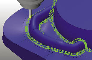
Courtesy of Surfware
Automated rest machining is one of the new high-speed machining toolpaths in SURFCAM Velocity 4.
The rest machining functionality automatically calculates the areas where material remains after the previous operation and generates a toolpath in these areas. There is no need to manually create boundaries. The rest machining differentiates between near horizontal and near vertical corners, and it uses the best-suited cutting strategy to machine them.
The 3-D offset finishing feature provides a fine surface finish regardless of part shape. A constant scallop height is ensured by passes that are at a constant distance from each other along a surface.
To also impart an excellent finish, the software uses offset pencil milling passes to machine a part's corners. It is possible to make single or multiple offset pencil milling passes at a constant distance from each other.
The enhanced steep/shallow feature machines a part's steep and shallow regions as one operation by using the optimal machining strategy for each region. The feature can also enable machining only the steep or only the shallow regions. The adaptive step-down feature automatically modifies the toolpath to ensure this operation leaves a uniform amount of workpiece material.
Smooth and tangential linking moves between the passes enable maximum speeds and feeds. In earlier versions, the retracts consisted of orthogonal rapid moves to the rapid plane. In SURFCAM Velocity 4, these moves are optimized for the part topography, thereby shortening the machining cycle.
Processing speed, powered by multiple processors, is up to 80 percent faster than the previous SURFCAM version, which provides significant time savings.
With SURFCAM's simultaneous 4- and 5-axis machining, full visualization and verification, machinists gain control over multiple-axis machining, ensuring safe tool motion in challenging applications. The multiple-axis module provides support for standard tools with collision checking, gouge avoidance and toolpath containment.
More gouge avoidance strategies have been implemented in the latest version. Users can specify four different cascading tool gouge strategies, which can be applied to a single operation.
Additional tool control has been added to swarf cutting to allow the tool to be tilted away from the surface to better control the cut. Better surface edge controls have been added to handle geometric inconsistencies found in imported geometries. Axial adjustments to allow tool shifting in respect to the calculated cut point give the programmer added control when needed.
Full surface edge and gap handling has been added, and seven different lead-in and lead-out options can be applied to control tool motion during any event in the cutting process.
New retract types, including plane, cylinder and sphere, allow machinists to tailor the retract motion to be closer to the part type and orientation.
In SURFCAM Velocity 4, an enhanced, intuitive user interface was a key focus. In addition, the help documentation provides up-to-date and useful knowledge that is easily accessible.
The product is available with TrueMill, Surfware's toolpath technology that manages tool engagement to increase productivity and extend tool life. CTE
About the Author: Sashko Kurciski is product manager for Surfware Inc., Camarillo, Calif. For more information about the company's CAD/CAM software, call (818) 991-1960, visit www.surfware.com or enter #390 on the IS Card.


