Through-coolant toolholders: efficient, economical
Through-coolant toolholders: efficient, economical
Because through-coolant toolholders eliminate the variances often experienced with external cooling nozzles, the additional cost of such holders, which is sometimes zero, can be easily justified through the reduction of cycle times and improvement of tool life and part quality.
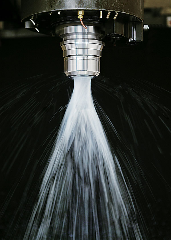 Imagine that this nightmare machining scenario has just hit: Your tool life suddenly shrinks from 100 parts to 10 parts, the surface finish of your workpiece rapidly degenerates and—worst of all—an endmill breaks in the toolholder.
Quick: What do you check first?
According to Drew Strauchen, vice president of marketing and business development for Haimer USA LLC, Villa Park, Ill., machinists often run down five or six rabbit holes and spend a lot of time and money investigating the cause of the problem before they think, " 'Wait—how are we delivering coolant here?' "
"It's usually one of the last things they check," he said.
Applying coolant while machining is important for two related reasons: It keeps the cutting tool edge cool and clears chips from the cutting zone.
According to Chelsea, Mich.-based Advanced Industries Inc.'s Chris Beckington, whose company makes KoolBlast toolholders, coolant is especially important when machining with carbide tools. "The thermal stress of heat caused by friction in the cutting zone can wear out the carbide," he said. "This alternate heating and cooling causes weakness in the tool, so we try to [constantly] keep … coolant on the tool to eliminate the effects of thermal shock."
There are three basic ways to apply coolant during machining. The most common way is with external nozzles—a process called flood cooling. However, problems often occur with this type of system. For example, copper flood coolant lines are fixed to the machining head so they don't move. But when machining parts with features such as a shoulder or a ledge, the tool can dip down below that ledge to work at the bottom of a surface, blocking coolant from reaching the cutting zone.
Similarly, flood coolant systems incorporating flexible plastic nozzles often aren't positioned properly, "because the operator assumed positioning does not matter," Strauchen said, "or, more likely, something happened during a machining process or a tool change where the nozzles got bumped and are no longer directing coolant anywhere near where they're supposed to."
A second method of applying coolant is to run it through the tool itself. This is the most accurate way to direct coolant to the cutting zone, but tools with through-coolant capability are mostly limited to drills, Strauchen said.
"In the majority of cases for endmills, the coolant's either being fed externally with nozzles or it's coming through the toolholder," he said.
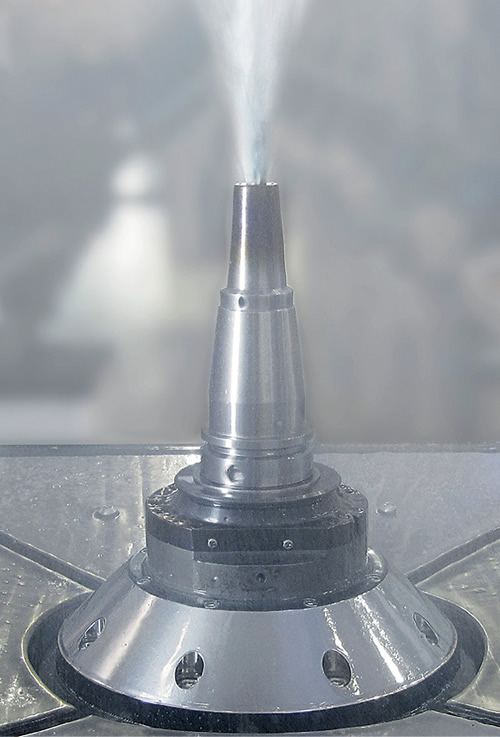
Through-coolant toolholders—the third method of coolant delivery—have one or more internal coolant passages. Coolant runs through the spindle, all the way up to the nose of the holder, where it exits two or more ports located close to the shaft of the tool. The toolholders, which are typically modified standards, come with a range of port styles, from simple holes bored with an EDM to elaborate angled passageways running through the chuck.

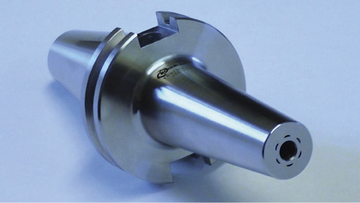
The KoolBlast Thermalfit through-coolant toolholder from Advanced Industries features D-shaped orifices and the company's PressureMax design, which together minimize turbulence as coolant contacts the cutting tool. Image courtesy Advanced Industries.

Because through-coolant toolholders eliminate the variances often experienced with external cooling nozzles, the additional cost of such holders, which is sometimes zero, can be easily justified through the reduction of cycle times and improvement of tool life and part quality.
"Any time there is an unplanned stoppage due to tool breakage or additional rework added to a job to fix bad parts, a huge cost is incurred," Strauchen said. "We try to convey to people that a through-coolant toolholder is a
capital expenditure and should be implemented as a best practice. You're going to benefit for the next several years from it."
Types of Toolholders
Haimer offers Cool Jet and Cool Flash systems for its shrink-fit chucks. Cool Jet, which comes standard with nearly all Haimer shrink-fit holders, features angled internal bores in the walls of the holder that facilitate coolant exiting the nose of the chuck. Cool Flash is an upgradable option that has a series of T-slots around the ID of the chuck to apply coolant directly to the shank of a cutting tool. This option is particularly beneficial at higher speeds, where greater pressure is inherently needed.
BIG KAISER Precision Tooling Inc., Hoffman Estates, Ill., offers a line of through-coolant hydraulic chucks with two small holes on the face of the chuck angled to direct coolant down the endmill shank.

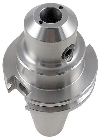
Pioneer through-coolant toolholders come with two orifices standard. The company will EDM additional holes for a charge. Image courtesy Pioneer.

It's rare to see through-coolant in a hydraulic chuck because it has a lot of internal features, making it difficult to get coolant around them and out, said Alan Miller, engineering manager at BIG KAISER. "We really only recommend hydraulic chucks for finishing endmills—it's typically going to be a ballnose endmill, probably in a 5-axis environment, to really get the benefit."
BIG KAISER also offers through-coolant features on several different series of collet chucks. "That gives you the versatility of a collet chuck program—to grab any tool size—whereas hydraulic chucks are more or less dedicated to one specific size," Miller said.
Advanced Industries makes two types of KoolBlast through-coolant toolholders: one series with a standard Weldon setscrew and a series of Thermalfit holders. Both use the same unique internal coolant distribution design, according to Beckington.
Pioneer N.A. does things a little differently. It will EDM through-coolant holes into any of the toolholders it inventories.
"We put in two holes standard, but we charge $20 per additional hole, so if a customer has enough coolant volume coming through the machine to support it, we can put in more," said Lee Flick of Pioneer, Elk Grove Village, Ill. "We've done as many as 12 holes in a holder for one of our customers."
Pressure Situations
Flick said the amount of coolant pressure available will dictate how fast a tool can run and yield effective results, based on how fast the coolant evacuates chips. "If you have enough pressure to support it, the more holes you have, the faster you're going to be able to cut, and the longer your cutting tools are going to last," he said.
Flick noted that a lot of older machines have 50-psi coolant pumps while many newer machines are equipped with 1,000-psi systems. "Most of these higher-pressure machines can run at 20,000 rpm because they have enough coolant pressure, while the older machines are probably running 3,000 or 4,000 rpm."

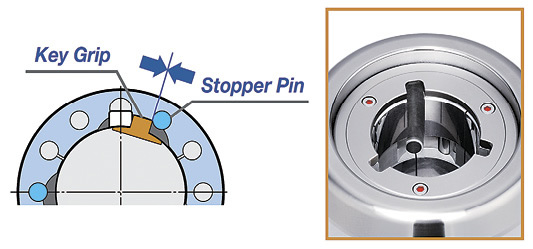
The Mega Perfect Grip holder from BIG KAISER is designed for applications involving superalloys. It incorporates a key grip that locks the Weldon flat of a cutting tool into place. Three slots in the bore where the key can slide down provide holes for the higher volume of coolant needed to machine such materials. Image courtesy BIG KAISER.

Similar to placing your thumb over the end of a garden hose, the design of a through-coolant toolholder can help increase the pressure of the coolant hitting the cutting surface.
"If your area for delivering coolant is reduced, the laws of physics dictate that the force at which the liquid leaves the holder will be greater," said Haimer's Strauchen. "So somebody who has limited coolant pressure of only about 150 to 300 psi can maintain proper cooling without diffusion at high speeds (up to 18,000 rpm), where they would otherwise need 600 to 750 psi to maintain proper cooling."
Designing an effective through-coolant toolholder requires an understanding of the "vortex effect." As the tool rotates at higher and higher speeds, it whips up a vortex of air, which creates a barrier that can prevent coolant from reaching the tool/workpiece interface.
Toolholder companies have developed a number of creative ways to try to overcome the vortex effect and ensure that coolant meets its mark at higher speeds. The standard design uses round holes situated about 1mm (0.039") from the tool shank, requiring the coolant spray to "travel" a bit before it touches the shank.
KoolBlast developed a unique D-shaped orifice design for its new Thermalfit through-coolant toolholders, along with patented internal passageways that pressurize the coolant before releasing it. "With our new design, coolant exits at a specific angle and location so that it hits the tool in a way that maximizes the velocity while fighting through the turbulence from the centrifugal force that prevents it from reaching the cutter," Beckington said.

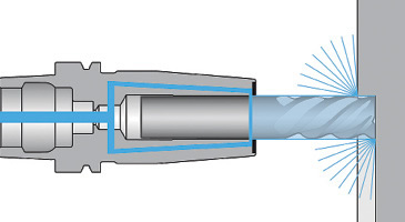
Haimer's Cool Flash toolholder system was designed to direct coolant to a tool's surface with no air gap. Coolant collects in a chamber in the holder then is distributed evenly over the entire circumference of the tool shank. Images courtesy Haimer.
Similarly, Haimer designed its circular Cool Jet bores to run at 3° angles so that as coolant exits the toolholder, it is aimed directly at the cutting edge. "But even so, when you rotate fast enough, the separation still makes it easier to atomize," Strauchen said.
This led the company to upgrade its design to one that would deliver the coolant directly to the tool shank with no air gap. "What makes our Cool Flash system unique is that the coolant exits through small perpendicular slits located around the internal diameter of the toolholder," Strauchen explained. "This not only helps coolant reach the shank, because it's being directed straight onto it, but by taking advantage of surface tension and centrifugal forces, the coolant is actually being spun up the shank of the tool. So, centrifugal forces are working for us instead of against us."
Maintaining Balance
With a rotating tool, balance is critical in terms of productivity, accuracy and finish.
"For some through-coolant systems with add-on parts, like sleeves that fit over a toolholder, you run the risk of putting the assembly out of balance," Strauchen said, "and the faster it rotates, the more that imbalance will cause vibration in the spindle, which can lead to chatter, degraded tool life and less productivity."
Maintaining accurate balance is the reason that Haimer designed its Cool Flash system with a permanent, laser-welded cap on the chuck, Strauchen said. "This way there's no moving parts, and no fear of throwing the balance out of specification."
For Pioneer toolholders, the company offers customers the option of having their tool assemblies rebalanced once the coolant holes have been drilled. "We recommend they send us their cutter, and we'll put the tool into the toolholder, put it on the balancing machine and trim up the whole assembly based on how fast they intend to run it, whether it's 5,000 rpm or 20,000 rpm," Pioneer's Flick said.
Choosing a through-coolant toolholder depends a lot on the application. For example, BIG KAISER's Mega Perfect Grip toolholder was designed specifically for milling heat-resistant superalloys.
"There's so much axial force when the cutting tool engages with these materials, it tries to physically pull the cutting tool out," Miller said, "and the forces can get so high that even with very strong clamping forces, they can slip."
To counteract these strong forces, the Mega Perfect incorporates a key grip that locks the Weldon flat of a cutting tool into place. In addition, the three slots in the bore where the key can slide down provide holes for the higher volume of coolant delivery needed for these types of applications.
"High-temperature alloys need a lot of coolant volume, but not necessarily a lot of pressure," Miller said. "The higher volume is required for better heat transfer, because you don't want these materials to get too hot or they'll workharden and get more difficult to machine."
In some cases, coolant may not even be desirable. "When you get into steels, a lot of times you'll be doing more roughing work, and the coating technologies of these tools work better without coolant, though people will still use air to get chips out of the way," Miller said.
Whatever the material, through-coolant toolholders provide numerous benefits. "You get increased tool life because you're keeping the cutter cool, so you can cut faster and get better surface finishes," said Advanced Industries' Beckington.
"You can also control your chip evacuation better, compared to flood coolant," he added, and the coolant is "more centralized to the cutting area, so you're evacuating chips in pockets and cavities and not recutting them. It helps you keep a nice clean workspace where you're cutting."
Flick said a lot of customers initially are skeptical that adding through-coolant capability to a toolholder will do much good. "They just don't get it," he said. "So when we go into their shop and actually run it for them, they're blown away at the difference it makes—and for a very small upcharge."

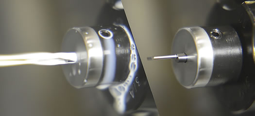
Scientific Cutting Tools' Coolant Ring Technology toolholder provides a 360° coolant delivery pattern. Image courtesy Scientific Cutting Tools.
Toolholders that supply a cool blast
There's more than one way to direct coolant onto a tool's cutting edges using through-coolant toolholders.
One method is Coolant Ring Technology toolholders from Scientific Cutting Tools Inc., Simi Valley, Calif., which reportedly enhance coolant penetration, such as into a bore. In that scenario with a conventional through-coolant holder, coolant hits the face of the part and splashes back. The CRT holder, on the other hand, delivers coolant all the way around a tool instead of one quadrant of the tool, so wherever there is space to get into the bore, coolant is there. The result, said Scientific, is a 75 percent higher level of coolant penetration.
By effectively delivering coolant to the cutting tip, SCT stated that the tip will only be a couple of degrees warmer than the coolant temperature. But if there is not an ample supply of coolant to the tip, the tool can get hot enough to negatively impact the carbide binder and deformation of the carbide can occur. Also, heat can cause a part to thermally expand and make it difficult to hold a tight tolerance.


