Tooling Trends
Tooling Trends
This article provides a review of the research and technology trends that will shape metalcutting in the years to come. Innovations in workpiece materials, coatings, machine tool design and nontraditional machining are explored.
Better, faster, harder, and more precise are the omnipresent demands of the metalcutting industry. The goal is to improve efficiency, reduce costs, boost productivity, and minimize cycle times. New materials, advanced coatings, and nontraditional cutting techniques are being developed to yield longer tool life.
Cutting tool manufacturers are working with both their customers and with the developers of new, high-performance workpiece materials to develop new tools and the application information that will be needed to optimize machining productivity in the future.
Using advanced computing tools like 3-D simulation and finite element analysis (FEA), manufacturers and researchers at university and federal government labs are predicting cutting tool performance and deploying the most suitable tool for an application. The same techniques also are used to measure the effectiveness of various coating processes with various tool materials.
Total system design, simulation, and process control are leading the R&D efforts for cutting tools. A comprehensive system design in cutting tool technology extends beyond the tool, workpiece material, and machining parameters to include a tool's inherent characteristics dependent on its substrate, coatings, and style.
For instance, a coating applied to a given substrate may be expected to deliver predefined cutting characteristics when used with a workpiece material. However, once heat and force in a machining operation enter the equation, reactions between the workpiece material, substrate, and coating become unpredictable.
"Drivers of change in manufacturing, including requirements to reduce fuel consumption, optimize manufacturing processes, and protect the environment, have initiated major and continuing changes in workpiece materials and processes," says Friedrich Momper, technical director, Kennametal Hertel AG, Furth, Germany.
"These changes will require cutting tools that are tailored to endure the specific machining conditions that new materials present. For instance, a focus on dry machining will drive efforts in developing cutting tools with higher resistance to thermal load and fatigue."
Jerry Reimann, a program manager at the Ann Arbor, MI-based National Center for Manufacturing Sciences and director of its Technology Research Corp., says the biggest design changes are occurring in two areas: cutting tool materials and workpiece materials.
Material Gains
"In cutting tool materials, there are more unusual types of coatings like diamond film," Reimann says. "These coatings were introduced into the market based on research, but continued research is needed to make these films more robust by tweaking the process. It's been great on some of the high-silicon aluminum. We are trying to advance to tougher materials like aluminum metal matrix and ceramic-matrix composites.
Another coating that's interesting is cubic boron nitride (CBN) as a film."
"Today, there are a lot more unusual materials hitting machine shops, like aluminum metal matrix and polymer composites, because industry wants stronger, lighter weight materials and it all starts with development of the cutting tool," explains Reimann. "In the area of aluminum metal matrix, the Aluminum Metal Matrix Composites Consortium was formed in the last six months to look at machining and material removal."
A good example of the evolution of workpiece materials is the increased use of aluminum alloys in automotive manufacturing. In 1980, approximately 3% of a typical mid-size car was made with aluminum. By 1990, that percentage had risen to 5%. "Forecasts for future cars predict usage of aluminum will rise between 10% and 20%," says Kennametal's Momper, "with engine blocks, cylinder heads, and housings being major contributors to consumption. In brake disc rotors, aluminum alloys with high silicon contents may replace gray cast iron.
"Another new breed of material is compacted cast iron, which offers higher toughness as well as weight reduction on the order of 30% compared to gray cast iron," adds Momper. "Compacted cast irons are finding increased use in vehicular components such as diesel engine blocks. However, compacted cast iron is harder to machine than gray iron. New coatings and coating processes, such as titanium aluminum nitride (TiA1N) and physical vapor deposition (PVD), can overcome the drop in productivity that might result when machining such abrasive workpiece materials."
Surface Coatings
Although uncoated carbides and polycrystalline diamond tools currently dominate the turning, milling, and drilling of aluminum alloys, the increasing use of these materials will hasten further development of diamond-coated cutting tools during the next five years.
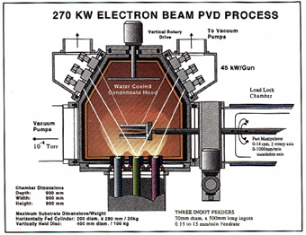
Fig 1: The EB-PVD coating process used by Penn State University's Applied Research LabElectron beam physical vapor deposition (EB-PVD) research is being conducted at Penn State University's Applied Research Lab in State College, PA. Research in material coatings technology using EB-PVD melts the coating material made from metal, alloy, or ceramic, vaporizes it in a vacuum, and deposits the material on a component or part that requires the surface properties inherent in the coating (Figure 1). EB-PVD technology is based on work that originated at the Paton Welding Institute of the Ukraine Academy of Sciences.
"We are hoping to develop multilayered titanium carbide (TiC) and titanium diboride (TiB2) coatings for cutting tools on commercially produced tool steel substrates to machine titanium and nickel-base super alloys," says J. Thomas Schriemph, assistant director, high energy processing division. "This is expected to extend tool life by a factor of two or three."
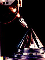
Fig 2: The large-optics diamond turning machine at Lawrence Livermore National LaboratoryResearchers at Lawrence Livermore National Laboratory, Livermore, CA, are currently looking at diamond and CBN for use with its large-optics diamond turning machine (Figure 2). The machine can handle parts up to 5'-dia., 18"-high, weighing up to 3000 lb. It is used to machine some nonferrous metals such as copper, gold, aluminum, and nickel, in addition to brittle materials like nonlinear crystal KDP (potassium dihydrogen phosphate).
Because some materials, including steel, titanium, and beryllium, react chemically with the diamond point, Livermore researchers have experimented with single-crystal CBN, which is stable and strong in high temperatures, as an alternative to a diamond tool. Early trials have shown that single-crystal CBN is too delicate for use in machining. So instead, the lab is developing diamond turning tools that are coated with CBN and other hard materials that allow the tool to maintain its sharp edge.
Livermore's vacuum-process laboratory (VPL) employs PVD methods to apply coatings. Its cathodic-arc process competes with electron beam and magnetron sputtering in vacuum-coating technologies. Cathodic arc is an electrical discharge in a vacuum, which is sustained in the metal plasma created by the arc alone so it does not require the addition of an inert gas.
Currents used in cathodic-arc systems are high current and low voltage—approximately 100 amps at about 30v so that most of the metal vapor generated by the arc is ionized by the discharge. The trajectory of these ions is controlled as they travel from source to substrate, and the energy with which ions impinge on the substrate also is controlled. With electron-beam evaporation and magnetron sputtering, most of the atoms of coating material travel from the source to the part and are then coated in an electrically neutral state.
By adjusting the deposition energy, coatings with greater density, purity, and adhesion are produced. The VPL is working with two manufacturing companies to develop new source configurations and coating applications for this technology. One application, amorphous diamond (a:D) coatings, is produced on cooled substrates (room temperature and below) and is hard, electrically insulating, inert, and transparent. Diamond-film research has focused on reducing the temperature of deposition, improving the adhesion to various substrates, lowering residual stress, and reducing surface roughness.
The Spindle Is the Tool
Research at Massachusetts Institute of Technology (MIT), Cambridge, MA, has culminated in numerous machine tool components, among them a hydrostatic spindle that operates at 100,000 rpm with 100kW of cutting power. The TurboTool is a football-sized spindle made with a single monolithic shaft that was designed by Alexander Slocum, a mechanical engineering professor at MIT. A cutting tool, self-compensating water hydrostatic bearings, and turbine-drive blades are all machined onto a shaft that's powered by a high-pressure, high-flow, pump/filter system.
The coolant used to power the turbine and bearings flushes away chips. Coolant and chips are then separated centrifugally, producing dry cake at one end and micron-clean coolant at the other. The coolant can then be recirculated to the spindle.
According to Slocum, shear-power losses in the HydroSpindle's shaft-surface hydrostatic bearings are about equal to the losses in a state-of-the-art hybrid ball bearing milling spindle running at 50,000 rpm. Because higher pressures used for higher turbine power result in greater radial load capacity in the bearings, the design is always balanced.
The tool is located in a front housing, with self-compensating, radial-hydrostatic-bearing features formed directly into the tool shaft. Slocum claims the special HydroSpindle bearings are not subject to whirl-instability like conventional fluid bearings.
In the event of a crash, the hydrostatic bearings cushion the impact. In severe accidents, a screw-thread-type seal in the tool acts as a stress point, and the tool breaks off. The power source is remote from the spindle, so it will not be affected by a crash.
The tool itself is loaded into the housing in a toolroom and can be held by a standard HSK or CAT interface. The spindle also was designed with a through-coolant delivery system.
Other MIT designs include a modular self-compensating hydrostatic linear-bearing system, a damper base for precision machine tools, and a machining-variation-analysis software program. Slocum and former MIT colleague, Kevin Wasson, have formed a Concord, NH-based company called Aesop Inc. to develop commercial applications for the high-speed spindle.
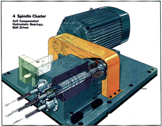
Fig 3: The TurboTool spindle operates at 100,000 rpm with 100kW of cutting power using hydrostatic bearings.The National Center for Manufacturing Sciences recently tested the TurboTool in a four-spindle cluster at its facility (Figure 3). "We have a project underway with an ultra-high-speed spindle [100,000 rpm/100kW] using the TurboTool," says Jack McCabe. "We had a meeting to see who would want to participate using the spindle cluster on a hexapod, mostly for aerospace applications, but couldn't find a commercial end user. However, the spindle has been built, and we are waiting for test results."
Simulation Tools
Researchers at MIT have developed a software solution based on an integrated system design called machining variational analysis (MVA). It predicts the true shape of a manufactured part, taking into account the effects of random and systematic variation based on the nominal geometry of the part, the construction of the machine, the shape of the cutting tool, and sources of error in the machine's operation. The sources of error can include machine parametric error, fixturing error, or sensor noise.
The calculated shape is used to compute the expected values of any tolerances held on the part as defined in geometric dimensioning and tolerancing, including size, location, and form. The MVA software uses new algorithms to compute the swept envelope of the cutting tool as it moves with respect to the workpiece.
Four mathematical techniques are integrated into the MVA program —homogenous transformation matrices (HTMs) create a complete kinematic model of a machine tool; envelope theory maps the cutting tool shape and motion onto a workpiece's geometry; error signature provides a pattern of error associated with each error source; and Monte Carlo simulation uses random number generators to perform probable simulations.
Nuri Akgerman, associate director of the Engineering Research Center for Net Shape Manufacturing at Ohio State University, Columbus, OH, believes that the weak link is the tool material. "Materials like PCBN are encouraging," says Akgerman. "However, the way you cut with them needs to be controlled very tightly and the motions need to be programmed very tightly. Today's CAD/CAM systems only work with geometry. Software needs to bring in technological parameters."
According to Akgerman, cutting strategy should consider cutting mechanics (e.g., how a cut is entered, etc.). However, a very serious limitation occurs when a cutting tool comes to a corner and turns around, because the motion is slowed down. Once the tool slows, the chip load per tooth suddenly goes very low, and the tool starts burning and rubbing the material instead of cutting it. In addition, when moving into a corner, the tool is overloaded.
"All these things need to be considered in detail when creating the cutter path," explains Akgerman. "Just going for the harder tools and the different materials aren't going to do it. In fact, we've found that if you are not very careful how to go into that cut and how to stay within it, expensive tools are a waste of money because they will break away. We are working on developing software for this problem and are looking for a CAM supplier, but so far no one has stepped up."
Alternative Cutting
Researchers also are exploring nontraditional techniques on hard-to-machine materials. For instance, cryogenic machining, where liquid nitrogen is delivered to the cutting tool to reduce machining temperatures, is getting attention at several universities, such as Penn State and Nebraska. Research is focusing on the types of cutting tool materials that are able to withstand low-temperature thermal shock. Researchers also are developing the machining strategy and cutting conditions for a cryogenically-cooled application.
A program currently underway at the University of Nebraska, Lincoln, transports liquid nitrogen to a reserve near the rear of the cutting insert to reduce its temperature. Experiments include machining ceramics with cryogenically cooled inserts consisting of CBN50, VC722, and VS734, and titanium alloys machined with carbide inserts. Early results indicate both tool wear and surface-quality improvements.
In Germany, research is geared toward transferring the tribologic functions of the cutting fluids to the tool material using different coatings. Chip carry-off methods in dry or nearly dry machining conditions include compressed air, electromagnetically charged steel plates, and water rinses.
The search for an alternative cutting technology for hard-to-machine materials led Lawrence Livermore National Laboratory engineers to develop a workstation for the femtosecond laser cutter. The laser, originally developed for defense purposes, delivers pulses lasting just 50 to 1000 femtoseconds (quadrillionths of a second), ionizing the material and removing it atom by atom. The femtosecond workstation uses ultrasonic sensor technology to locate and mark the cut.
Cutting occurs in a vacuum chamber with diagnostic cameras measuring the cut. The laser's ultrashort pulses are too brief to transfer heat or shock to the material being cut, so there is virtually no damage to surrounding material. Conventional lasers, diamond saws, and water jets cannot achieve the precision of the laser machine tool (0.1mm), and most of those machines damage surrounding material to varying degrees.
Because only a thin layer of material is removed during each pulse of the laser, the cut surface is smooth and does not require cleanup.
About the Author
Melissa Kennedy is a freelance business writer based in Cleveland who specializes in the metalworking industry.


