When chatter chirps, what’s your first reaction? Do you quickly grab the spindle speed override, slowing the machine so you can increase the chip load per tooth? If so, you’re not alone, but there are better ways to avoid chatter and improve surface finishes. In addition to traditional mechanical methods, new control technology can assist the operator in selecting speeds and feeds that help cut the chatter.
Chatter is caused by the inherent natural frequency of a cutting tool. The natural frequency can be affected by many process conditions: the toolholder, cutter tooling, part fixtures and machine condition. Chatter creates surface finish problems, which can be profit-killers because they compromise part quality, create scrap, delay deliveries and destroy perishable tooling. The following are some of the techniques commonly employed to combat chatter. Use these guidelines to establish a firm foundation for optimizing machining processes.

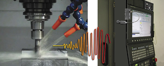
Machining Navi M-i measures chatter vibration using built-in sensors and automatically changes the spindle speed to the optimal rpm. All images courtesy Okuma America.
Common toolholders, such as side-lock holders, double-angle collets and standard ER collets, don’t provide the accuracy or stiffness needed for high-performance machining. A better option is a toolholder shank that incorporates face and taper contact to enhance accuracy and rigidity. This type of holder provides simultaneous contact between the precision ground spindle face and spindle taper, which increases rigidity and aids damping.
All appropriate rotating tools, such as endmills, facemills, drills and boring bars, can be balanced. It’s always best to balance at the highest expected spindle speed. This improves surface finishes even at low spindle speeds.
Because cutting tools can greatly influence chatter generation, a tool should be optimized with the proper substrate, geometry, coating and length-to-diameter ratio for the application. One effective way to reduce vibration is by applying tools with variable-flute geometries. Also be aware that programmers often gravitate to using the largest tool that can “fit,” but that may not be ideal.
In addition, if a part is not properly secured, it can vibrate and induce chatter. When the fixture is not designed to provide natural damping, the frequency from the fixture can trigger a tuning-fork effect. Many excellent workholders are available to clamp workpieces, but the criteria to focus on includes level of precision, clamping force, ease of use and flexibility to allow use across multiple machine tool platforms.
If you’re trying to impart fine finishes and hold tight tolerances on a poorly maintained machine, you’ll need to overcome mechanical challenges well beyond the issues listed here. Therefore, it’s critical to perform regularly scheduled maintenance on equipment to ensure the best performance.
These methods and practices can correct some causes of chatter, but will only go so far. Machining Navi is a new control technology from Okuma America that goes beyond the basics and can automatically recommend the “sweet spot” rpm for a cut, which might be faster than the one that causes chatter. The goal is to maximize machine tool performance.

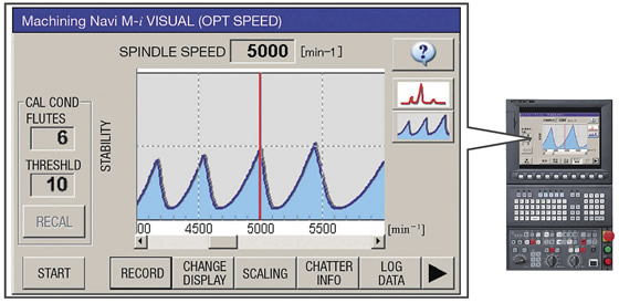
When chatter occurs, this Machining Navi M-i screen is shown on the OSP control, override is used, and the spindle speed is changed to the peak one.
For milling, Machining Navi M-i intelligently optimizes spindle speed control. Chatter vibration is measured by built-in sensors, and spindle speed can be automatically adjusted to the optimal rpm. In addition, advanced graphics of the optimal cutting conditions show effective alternatives to suppress various chatter characteristics throughout the low- to high-speed zones. This auto-mode enables operators to quickly and easily find the ideal cutting conditions.
The control technology also guides an operator to the optimal spindle speed. Using chatter noise detected by a microphone, Machining Navi M-g displays the best options for a chatter-free spindle speed. The operator then selects a recommended speed and immediately confirms the result.
For turning, Machining Navi L-g guides the harmonic spindle speed control. This allows chatter in a lathe to be suppressed by changing the spindle speed to one with the ideal amplitude and wave cycle.
Okuma ran Machining Navi during a test cut with a machine running at 1,200 rpm when chatter was detected. Instead of slowing the spindle, which operators typically do when chatter occurs, Machining Navi determined that 1,266 rpm would be optimal and recommended that speed. If the machine had been slowed, the sweet spot would have been completely missed.
When chatter is suppressed by increasing the spindle speed, throughput increases. Machining Navi enables highly efficient processes, improves surface finishes and can even reduce tool costs. This helps machinists gets the most performance from their machines. CTE
Related Glossary Terms
- boring
boring
Enlarging a hole that already has been drilled or cored. Generally, it is an operation of truing the previously drilled hole with a single-point, lathe-type tool. Boring is essentially internal turning, in that usually a single-point cutting tool forms the internal shape. Some tools are available with two cutting edges to balance cutting forces.
- chatter
chatter
Condition of vibration involving the machine, workpiece and cutting tool. Once this condition arises, it is often self-sustaining until the problem is corrected. Chatter can be identified when lines or grooves appear at regular intervals in the workpiece. These lines or grooves are caused by the teeth of the cutter as they vibrate in and out of the workpiece and their spacing depends on the frequency of vibration.
- fixture
fixture
Device, often made in-house, that holds a specific workpiece. See jig; modular fixturing.
- gang cutting ( milling)
gang cutting ( milling)
Machining with several cutters mounted on a single arbor, generally for simultaneous cutting.
- lathe
lathe
Turning machine capable of sawing, milling, grinding, gear-cutting, drilling, reaming, boring, threading, facing, chamfering, grooving, knurling, spinning, parting, necking, taper-cutting, and cam- and eccentric-cutting, as well as step- and straight-turning. Comes in a variety of forms, ranging from manual to semiautomatic to fully automatic, with major types being engine lathes, turning and contouring lathes, turret lathes and numerical-control lathes. The engine lathe consists of a headstock and spindle, tailstock, bed, carriage (complete with apron) and cross slides. Features include gear- (speed) and feed-selector levers, toolpost, compound rest, lead screw and reversing lead screw, threading dial and rapid-traverse lever. Special lathe types include through-the-spindle, camshaft and crankshaft, brake drum and rotor, spinning and gun-barrel machines. Toolroom and bench lathes are used for precision work; the former for tool-and-die work and similar tasks, the latter for small workpieces (instruments, watches), normally without a power feed. Models are typically designated according to their “swing,” or the largest-diameter workpiece that can be rotated; bed length, or the distance between centers; and horsepower generated. See turning machine.
- milling
milling
Machining operation in which metal or other material is removed by applying power to a rotating cutter. In vertical milling, the cutting tool is mounted vertically on the spindle. In horizontal milling, the cutting tool is mounted horizontally, either directly on the spindle or on an arbor. Horizontal milling is further broken down into conventional milling, where the cutter rotates opposite the direction of feed, or “up” into the workpiece; and climb milling, where the cutter rotates in the direction of feed, or “down” into the workpiece. Milling operations include plane or surface milling, endmilling, facemilling, angle milling, form milling and profiling.
- shank
shank
Main body of a tool; the portion of a drill or similar end-held tool that fits into a collet, chuck or similar mounting device.
- stiffness
stiffness
1. Ability of a material or part to resist elastic deflection. 2. The rate of stress with respect to strain; the greater the stress required to produce a given strain, the stiffer the material is said to be. See dynamic stiffness; static stiffness.
- toolholder
toolholder
Secures a cutting tool during a machining operation. Basic types include block, cartridge, chuck, collet, fixed, modular, quick-change and rotating.
- turning
turning
Workpiece is held in a chuck, mounted on a face plate or secured between centers and rotated while a cutting tool, normally a single-point tool, is fed into it along its periphery or across its end or face. Takes the form of straight turning (cutting along the periphery of the workpiece); taper turning (creating a taper); step turning (turning different-size diameters on the same work); chamfering (beveling an edge or shoulder); facing (cutting on an end); turning threads (usually external but can be internal); roughing (high-volume metal removal); and finishing (final light cuts). Performed on lathes, turning centers, chucking machines, automatic screw machines and similar machines.


