CAM software takes the tension out of manufacturing lead times
CAM software takes the tension out of manufacturing lead times
Containing large-size cargo for transport is challenging yet necessary to keep bundles intact for individual orders and to keep them from flying off the beds of 18-wheelers at high speeds. Allstrap Inc., Upper Arlington, Ohio, specializes in the manufacture of the steel and poly straps that hold these sizeable loads together, as well as the pneumatic and battery-operated tensioning tools that keep the straps taut.

Containing large-size cargo for transport is challenging yet necessary to keep bundles intact for individual orders and to keep them from flying off the beds of 18-wheelers at high speeds. Allstrap Inc. specializes in the manufacture of the steel and poly straps that hold these sizeable loads together, as well as the pneumatic and battery-operated tensioning tools that keep the straps taut.
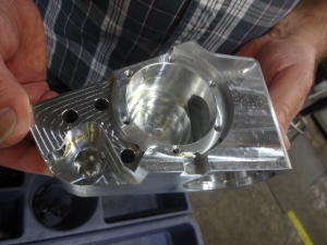
The housing for the C11 battery-operated strapping tool is machined from an aluminum block. Photos courtesy of CNC Software Inc. and Allstrap Inc.
Recently, Allstrap has seen an increase in demand for the battery-operated tools, which perform cutting, tensioning and sealing operations 30 to 50 percent faster than their pneumatic counterparts, with the touch of a button. To meet the need, the company has combined powerful Mastercam CAD/CAM software from CNC Software Inc., Tolland, Conn., with a 5-axis CNC universal milling machine to significantly reduce production time.
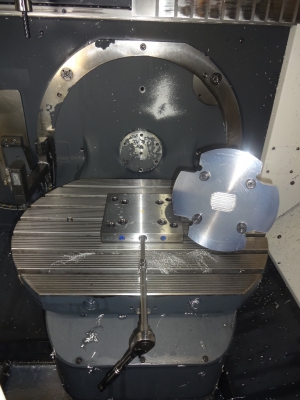
When running machines at high speeds, workholding equipment plays an important role in keeping the part in place and achieving tight tolerances.
Allstrap is located in the Columbus, Ohio, suburb of Upper Arlington, home of the Golden Bear high school teams and the birthplace of the Golden Bear himself, Jack Nicklaus. According to Allstrap President Josh Sikora, the company is the only shop that manufactures battery-powered strapping tools in the U.S. When designing their Golden Bear line of lashing, cord strap, strapping and steel strap tensioners, weight is of primary concern because operators carry them around on toolbelts all day. And, while the pneumatic tensioning tools have worked well for operators in the past, they prefer the speed and efficiency—they no longer need to pull a cord behind them—provided by battery power.
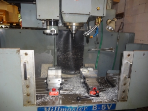
One workholder Allstrap relies on is the Chick OneLOK vice.
Tools are made from either aluminum, stainless steel or 4140 prehardened steel and weigh between 6 to 15 lbs. Between 25 to 100 components comprise each tool. Prototypes are made from aluminum because it is easy to cut through and mistakes are minimal. According to Sikora, once the concept for a tool and its parts are finalized, they will switch to either stainless or 4140 for the end product. About half of the final products are machined from aluminum and half from the stronger steels.
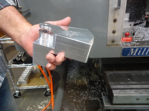
The Raptor Dovetail fixture securely holds parts even when large endmills are applied.
Allstrap was able to find the solution to the weight issue easily, but machining these stronger, lighter-weight steel materials without tool breakage and other mishaps in a reasonable amount of time, proved more difficult. The 3-axis machine it was using just wasn't efficient enough, and to optimize a new 5-axis CNC universal milling machine, the company needed to invest in a different CAD/CAM software package with features that would push the machine harder.
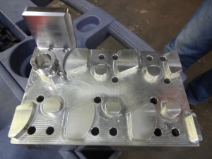
Six parts can fit on this workholding fixture.
Sikora had heard of Mastercam and contacted Kevin Richardson at FASTech Inc. (Reseller in Findlay, Ohio) whose experience with the software made the decision to purchase easy for Sikora. "I think Kevin has been the most experienced sales representative that we've had before we settled on Mastercam," he recalled. Richardson helped Sikora and his lead programmer Bob Freeman set up the software system and integrate it with the 5-axis machine. "We go from engineering design to manufacture," Sikora said. "When prototyping, we take the CAD drawing right from SolidWorks into Mastercam. Being able to jump into the 5-axis machine means you don't have all the stackups so we can move to the next model quickly."
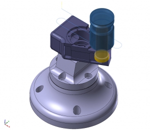
Because it's difficult to detect problems when running a machine at a high speed, Allstrap relies on CAM software to help prevent problems at the outset.
The combination of the new machine and the CAD/CAM software allowed the team to significantly reduce the time needed to make two of the tool components. But set up is integral to achieving this. According to Freeman, the machine has a 50-hp spindle, 60-position toolchanger and runs 600 psi through-the-tool coolant. "When you're machining at 18,000 rpm and running all that coolant, you really can't see what you're doing so you have to rely on your software to get that code where it needs to be or you're going to get lost fairly quickly and have problems," Freeman said.
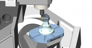
Mastercam's Productivity+ add-on allows Allstrap to program and simulate its Renishaw probe and laser system.
He stressed the importance of the workholding devices to keep things in place, especially when working with these large, high-performance endmills. Freeman uses the Raptor Dovetail fixture from Raptor Workholding Products, Burbank, Calif., which is designed to hold the part on 4- or 5-axis machines and can hold the materials securely even when the bigger endmills are used, and the Chick OneLOK workholding vice from Chick Workholding Solutions, Warrendale, Pa.
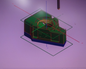
Mastercam's Dynamic Motion technology detects changes in part geometries and keeps the cutting tool constantly engaged in the workpiece material.
"The reason a lot of this is important," Freeman said, "is because the vice lets us precisely soft jaw a part on the machine table within a thousandth of an inch, which is close enough for the tolerances we're working with on the back of the part, and it makes the production work simply and accurately."
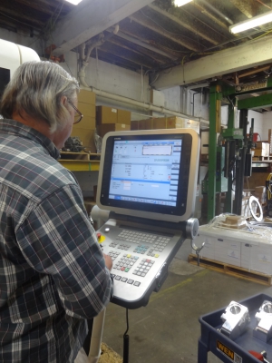
Bob Freeman programs Allstrap's 5-axis machine to produce the C11 housing.
Richardson connected Freeman and Sikora with IMCO Carbide Tool Inc., Perrysburg, Ohio, maker of 3- and 5-flute endmills and CGC Tools Inc., Waukesha, Wis, maker of Gorilla Mill Knuckledragger carbide roughing tools because the new system could handle them. The Knuckledragger is a 3/4-inch endmill with serrations and 1 5/8 of flute to cut with. Freeman runs it at 190 ipm at 12,700 rpm in 6061 aluminum.
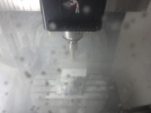
Allstrap runs the Gorilla Mill Knuckdragger 3/4" carbide roughing tool at 190 ipm and 12,700 rpm when cutting 6061 aluminum.
He does the math: "We're taking half the diameter of the cutter so that's 3/8 of an inch and we're cutting it 1.5 inches deep. At 190 ipm that would be 107 cubic inches per minute of material that we're removing," he said. "A typical 4.5- x 4.5- x 6-inch block disappears in just a few minutes at those rates." And because it's difficult to detect problems when running the machines at such speeds, Freeman relies on the software even more to help prevent problems at the outset. "It can be confusing to try to stop the machine to look at something because you often have 30 to 40 minutes of cutting time in and you might have 20 or 30 tools running."
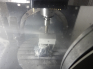
By combining Verify, Dynamic Motion and its tool library, Allstrap reduced manufacturing time from one hour per part to 22 minutes.
Freeman had 20 years of solid modeling and CAM software experience before going to FASTech to be trained on Mastercam. He found the systems to be big and robust and capable of running maybe 50 or more toolpaths in a single job. He also found that he could detect issues within the machine while running a job using the software's Productivity+ add-on, which allows him to program and simulate Allstrap's Renishaw probe and laser system, performing simple measurements and alignments to verify what is going on inside of the machine, saving downtime and giving him peace of mind. The ability to integrate the probe with the software allows him to use the former to its full capacity.
Allstrap takes half the diameter of the cutter, or 3/8", and cuts 1.5" deep in aluminum. At 190 ipm, the company removes 107 cu. in. per minute of material.
The tool library gives Freeman a database of his endmills so that modifications can be made quickly and easily. "It gives me a database to work from so that if today, I describe and load tool changers, and two weeks from now the software will tell me exactly how much tool I have sticking out of the tool holder and whether that tool and holder will be okay running in the machine according to our program," he said. He also creates stock models by initially programming a square material stock and then simulate the cutting operation. Sometimes three or four stock models are created for a particular application.
A typical 4.5" x 4.5" x 6" block of aluminum disappears in just a few minutes at high machining parameters.
Speeds of 180 to 190 ipm are possible using the software's Dynamic Motion technology, which, through the use of proprietary algorithms programmed into the software, detects changes in the geometries and keeps the tool constantly engaged in the material, reducing air cutting and tool breakage. No matter what the speed, even the bigger endmills automatically know where to go according to Freeman's program, blasting through the steel— even 4140—at high speeds.
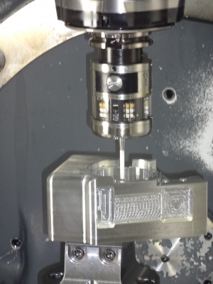
Mastercam's Productivity+ add-on performs measurements and alignments to verify what is going on inside the machine.
Freeman pointed out that he can take a solid model, and in a matter of five minutes, he can take 3 inches off his material running the machines at the 12,700 rpm at 190 ipm using the Knuckledragger endmill. The toolpath can be programmed in 5 minutes or less. "It would take an hour or more to program it the old way," he said, "because the toolpaths are fairly complex. It's a safe way to go because it figures out how to get on the part and where to get off, and its entry and exit motions are really something to behold."
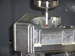
The ability to integrate the probe with the CAM software allows Allstrap to use the former to its full capacity.
After roughing, finishing routines are tailored to take leftover stock and create 3D geometries simply and easily. By combining Verify, Dynamic Motion and his tool library, Freeman was able to push his machine to formerly unimaginable speeds and reduced his manufacturing time from 1 hour per part to 22 minutes per part.
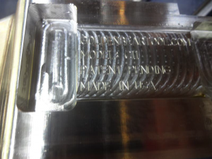
With Mastercam, Allstrap says time savings are significant when prototyping and producing tension tools to meet demand.
Sikora isn't as concerned about cost savings as he is time savings because material costs remain the same whether it takes 1 hour or 3 hours to make a part. Time savings are significant in being able to prototype and turn out tension tools to meet demand. Prototyping alone took a week or so with 60 to 70 hours spent on building fixtures, and another couple of days devoted to programming. If something went wrong during machining it could mean 2.5 to 3 weeks to make just one part. Both he and Freeman are grateful that they can move product along so that they can move on to the next project. "Once you become accustomed to utilizing the toolpaths, you just scratch your head at the time savings," Freeman said. "The software is so robust. There are so many different ways to grow in it depending on what your needs are."
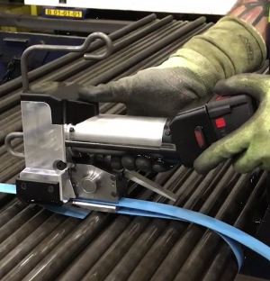
The Kodiak strapping tool bundling rod.
By doing their homework, making thoughtful investments and leveraging their combined experiences, the folks at Allstrap have pushed not only the equipment but also themselves to achieve time savings the company could only imagine. "When you run around and check a few other things while performing a job," Freeman said, "you find that the software, the machine, the tooling and the workholding all worked together in harmony to give you what it was that you wanted."


