Optimizing vibration-assisted drilling
Optimizing vibration-assisted drilling
Process optimization is key to increase the productivity and quality of the machining processes and thus ensure the competitiveness of machining companies. Valid measurements of physical parameters are necessary for the ideal assessment of optimization and measures as well as the efficient use of production resources at their performance limits. MITIS, a leading manufacturer of systems for vibration-assisted drilling, relies on measuring systems from Kistler for cutting force measurement.
Article from Kistler Instrumente AG
Process optimization is key to increase the productivity and quality of the machining processes and thus ensure the competitiveness of machining companies. Valid measurements of physical parameters are necessary for the ideal assessment of optimization and measures as well as the efficient use of production resources at their performance limits. MITIS, a leading manufacturer of systems for vibration-assisted drilling, relies on measuring systems from Kistler for cutting force measurement.
MITIS has been developing systems for vibration-assisted drilling for more than 10 years. Such systems are used particularly in applications where chip breaking plays a decisive role in achieving a stable and efficient process. In addition, the technology can extend tool life, increase cutting speed and improve machining quality. To analyze, understand and improve this new process, MITIS had to implement measuring solutions for machine tools from the very beginning.
In 2015, it was decided to take a further step towards automated machining tests on machine tools with the development of MITISlab. The aim was to implement an integrated solution for monitoring the machining tests on the in-house machining center and thus the possibility of systematically recording all machining tests. To carry out
this project, MITIS relied on its internal expertise in the development of the required software, which is now called WITIS, and the subsequent machine integration of the measurement hardware. The measurement hardware was purchased from different third-party vendors according to the requirements.
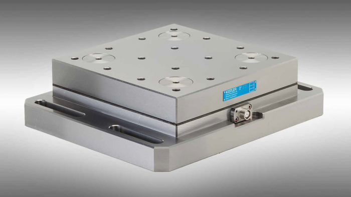
Figure 1: Cutting Force Dynamometer 9255C
The right choice of sensors as the basis for reliable measurement data
In particular, the measurement of cutting forces is indispensable for the evaluation of machining processes. MITIS relies on sensors from Kistler Instrumente AG for cutting force measurement. The Swiss company is specialized in the development of high-quality and robust piezoelectric sensors for cutting force measurement. The broad portfolio includes different systems, which are either
mounted stationary on the machine table or as a rotating solution in the tool spindle.
MITIS has opted for the stationary force dynamometer 9255C for its solution. The 9255C is one of the larger cutting dynamometers and, thanks to its generous clamping surface, offers plenty of space for the assembly of the test workpieces. Due to its robustness, a measuring range of up to 60 KN and its waterproof design, it meets all requirements for use in milling and drilling tests in the harsh environment of machining centers. In addition, piezoelectric technology ensures otherwise unattained accuracy, dynamics and rigidity. The high natural frequencies allow an analysis of the cutting forces resolved to the individual cutting edge.
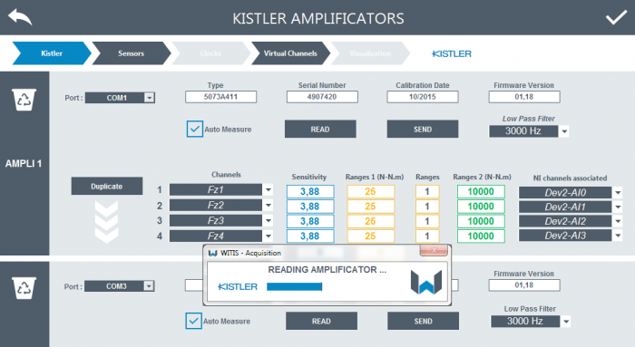
Figure 2: Parameterization of Kistler charge amplifiers within the WITIS Software.
A sensor does not make a measuring chain
A frequently underestimated component of measurement chains is the signal conditioning. The signal conditioning is responsible for the fact that the output signals of the sensors are converted and filtered in such a way that they can be adapted to the later application and acquired without loss of relevant information. It is also important that further information, such as scaling with the measuring signal, is transmitted to data acquisition. The output signals of the piezoelectric force dynamometer are electrical charges. Charge amplifiers are used to convert the charge signals
into voltage signals.
For this purpose, MITIS also relies on charge amplifiers from Kistler, which can be controlled and parameterized via a digital interface. This is the interface for the integration of the measurement hardware into the WITIS software from
MITIS. To simplify the operation of the system and to ensure that the parameters of the charge amplifier are stored
with the measurement files, MITIS has decided to implement a corresponding interface in the software, with which communication between data acquisition and charge amplifiers is possible. This enables the charge amplifiers to be parameterized directly from the software, so that the end user can manage all information and parameters in one environment.
WITIS was first developed by MITIS for the company's own needs. Designed by and for machinists, WITIS is easy-to-use, fast and reliable. The software was developed using LabView; it is compatible and can be flexibly adapted to the requirements of the application. The user has various tools for data analysis. This allows the data to be analyzed in the time domain as well as in the frequency domain.
Analyzing force signal is particularly relevant for optimizing vibration-assisted drilling applications. Indeed, the feed in VAD is a combination of the linear feed of the spindle axis and the small axial sinusoidal-form oscillation of the vibration assistance (incorporated into the MITIS toolholder). As a direct consequence the feed force is regularly varying between a minimal and a maximal level with a similar periodic form.
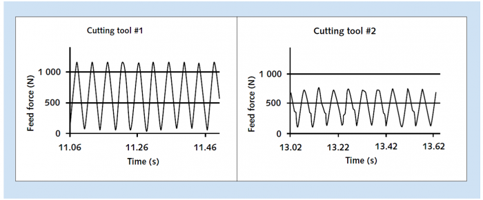
Figure 3: Feed force signal for both cutting tools in vibration-assisted drilling.
A perfect example of analyzing force signal in VAD is given in the following, dealing with drilling aircraft frames. In this case two cutting tool solutions (#1 and #2) must be benchmarked to find the one that combines both main requirements of client specifications: a maximal productivity (cycle time lower than 27 sec.) and a
minimal feed force in drilling (lower than 1000 N) to avoid deformation of flexible thin titanium parts.
The first step of the study consists in defining, for each cutting tool, the best VAD amplitude factor (i.e. a ratio VAD amplitude on feed per tooth) that provides an ideal fragmentation and evacuations of chips. Monitoring axial force during these tests is important to keep a minimal feed force higher to zero; indeed, this indicator ensures the user that the cutting tool is always remaining in the material while cutting. Amplitude Factor is found at 5.3 for cutting tool #1 and 4.0 for cutting tool #2.
Figure 3 shows respective axial force signal. Both signals have minimal values higher than zero but, for a same feed, cutting tool #1 shows a higher maximal force than cutting tool #2 because of its higher amplitude factor.
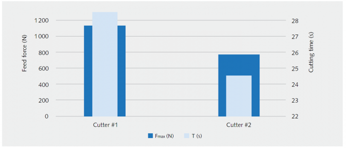
Figure 4: Maximal feed force and cycle time for both cutting tools #1 and #2.
Once the right amplitude factor has been chosen, the second step consists in defining feed and cutting speed to minimize both part deformation and cycle time together. As the deformation of the workpieces during drilling is strongly dependent on the feed force, a measurement of the forces by the Kistler sensor leads to a direct assessment of the process with regard to the influence on possible deformations.
For both cutting tools the maximum cutting speed is found at 18 m/min (diameter: 9.1 mm; lubrication: MQL). Consequently, process optimization must focus on the feed, considering that increasing the feed decreases the cycle time but also increases the axial thrust. Figure 4 shows cycle time and maximal axial force for both cutters. In this compromise race, only one cutting tool solution – cutting tool #2 – answers the client's needs. The other cutter generates such an axial force that favoring productivity is made to the detriment of quality (part deformation).


