Kentech Inc. announces the release of our new and enhanced versions of its KipwareM and KipwareT Conversational CNC Programming Software for Milling and Turning. Since its initial release back in 1999, Kipware conversational has allowed hundreds of shop floors to realize more efficient workflow by allowing non-CAD/CAM proficient chipmakers the opportunity to join in the programming process Kipware conversational was created upon the realization that the 95 percent of shop floor programming performed everyday in the real world, simple milling, drilling, turning, threading, grooving … does not require a CAD/CAM system nor a CAD/CAM programmer.
The addition of Kipware conversational allows shops to focus their CAD/CAM personnel on the more complex workpieces while the everyday programming is accomplished quickly and easily. With shops finding a shortage of skilled metalworking and CAD/CAM personnel, the use of Kipware conversational eases the programming burden and increases work flow. Building on customer feedback and "wish lists," the new versions of KipwareM and KipwareT really bring conversational programming to the next level with new features and enhancements built in a state-of-the-art user interface.
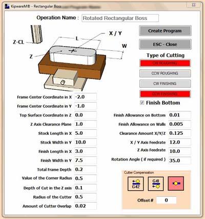
Using the power of Microsof's new .NET Version 4 Framework, the new Kipware conversational employs a vastly new and improved user interface built on the latest technology for the future. Any standard shape cycle created using Kipware's conversational, fill-in-the-blank forms can now be recalled and will appear once again in the conversational form. That means no G code experience is required as all program editing can now be done through the conversational menus. Users can have cycles created in the conversational menus auto-rotated to any user-defined angle by simply inputting it into the rotation angle field. Even TEXT/ENGRAVING can be autorotated at any angle. Users can easily LOAD previously created cycles from disk, EDIT them in the conversational menus, COPY cycles and quickly and easily edit them to create completely new cycles. These features mean faster programming and less redundant programming for items like family of parts or for re-ocurring shapes and features. New menus include both roughing and/or finishing in one menu. No need to program a roughing cycle then a finishing cycle; everything can now be done in one menu.
Users can select CW or CCW cutting for all milling cycles and can elect turning or facing type cutting for turning cycles. Individual directions can be selected for both roughing and finishing. For example, select CW for roughing and CCW for finishing or facing for roughing and turning for finishing. When finishing is selected for any conversational cycl the cutter compensation option can be selected and will be included automatically by KipwareM or KipwareT which will calculate and determine the start up move and include it in the finishing cycle. Drilling menus have been vastly redesigned and improved for faster and easier data entry and much greater flexibility.
Using the vastly enhanced KipwareTP option, users can select to plot an individual cycle or all the cycles in the Program Tree right from within KipwareM or KipwareT as the program is being created. For programming that does not fit into the "standard" shape conversational menu, users can use the included CAD like Kipware SketchPad to draw the desired toolpath or import a DXF file and create the G code through a conversational menu.
Contact Details
Related Glossary Terms
- computer numerical control ( CNC)
computer numerical control ( CNC)
Microprocessor-based controller dedicated to a machine tool that permits the creation or modification of parts. Programmed numerical control activates the machine’s servos and spindle drives and controls the various machining operations. See DNC, direct numerical control; NC, numerical control.
- computer-aided design ( CAD)
computer-aided design ( CAD)
Product-design functions performed with the help of computers and special software.
- conversational programming
conversational programming
Method for using plain English to produce G-code file without knowing G-code in order to program CNC machines.
- cutter compensation
cutter compensation
Feature that allows the operator to compensate for tool diameter, length, deflection and radius during a programmed machining cycle.
- family of parts
family of parts
Parts grouped by shape and size for efficient manufacturing.
- gang cutting ( milling)
gang cutting ( milling)
Machining with several cutters mounted on a single arbor, generally for simultaneous cutting.
- grooving
grooving
Machining grooves and shallow channels. Example: grooving ball-bearing raceways. Typically performed by tools that are capable of light cuts at high feed rates. Imparts high-quality finish.
- metalworking
metalworking
Any manufacturing process in which metal is processed or machined such that the workpiece is given a new shape. Broadly defined, the term includes processes such as design and layout, heat-treating, material handling and inspection.
- milling
milling
Machining operation in which metal or other material is removed by applying power to a rotating cutter. In vertical milling, the cutting tool is mounted vertically on the spindle. In horizontal milling, the cutting tool is mounted horizontally, either directly on the spindle or on an arbor. Horizontal milling is further broken down into conventional milling, where the cutter rotates opposite the direction of feed, or “up” into the workpiece; and climb milling, where the cutter rotates in the direction of feed, or “down” into the workpiece. Milling operations include plane or surface milling, endmilling, facemilling, angle milling, form milling and profiling.
- threading
threading
Process of both external (e.g., thread milling) and internal (e.g., tapping, thread milling) cutting, turning and rolling of threads into particular material. Standardized specifications are available to determine the desired results of the threading process. Numerous thread-series designations are written for specific applications. Threading often is performed on a lathe. Specifications such as thread height are critical in determining the strength of the threads. The material used is taken into consideration in determining the expected results of any particular application for that threaded piece. In external threading, a calculated depth is required as well as a particular angle to the cut. To perform internal threading, the exact diameter to bore the hole is critical before threading. The threads are distinguished from one another by the amount of tolerance and/or allowance that is specified. See turning.
- toolpath( cutter path)
toolpath( cutter path)
2-D or 3-D path generated by program code or a CAM system and followed by tool when machining a part.
- turning
turning
Workpiece is held in a chuck, mounted on a face plate or secured between centers and rotated while a cutting tool, normally a single-point tool, is fed into it along its periphery or across its end or face. Takes the form of straight turning (cutting along the periphery of the workpiece); taper turning (creating a taper); step turning (turning different-size diameters on the same work); chamfering (beveling an edge or shoulder); facing (cutting on an end); turning threads (usually external but can be internal); roughing (high-volume metal removal); and finishing (final light cuts). Performed on lathes, turning centers, chucking machines, automatic screw machines and similar machines.