Hyundai WIA has made considerable investments in recent years to develop machines to meet the unique needs of key industries, such as the mold and die market segment. This is easy to see in Hyundai WIA's all-new Hi-Mold Series of high speed machining centers. From the ground up, these machines were engineered specifically for the machining of precision molds. More and more mold makers are investing in equipment engineered specifically for the machining of molds. So, while in the past a basic vertical machining center might have been purchased to machine molds, today that's simply not practical.
To remain competitive in the global marketplace, mold makers must invest in technology better suited for mold making. That includes moving away from typical C-frame vertical machining centers accessorized for making molds to bridge-type VMC's, with spindle speeds to 40,000 rpm, thru spindle coolant and simultaneous 5-axis capability.
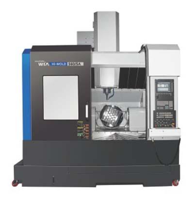
The HI-MOLD is a high speed bridge-type machining center particularly suited for precision machining due to the bridge design's high rigidity and the generation of low heat. The head of the main axis moves up and down and left and right on the cross beam. The table in turn moves front to rear. In order to eliminate thermal growth during machining, all axes are driven by high precision double-nut ballscrews. The double pretension design provides outstanding positioning and repeatability with virtually no thermal growth. All ballscrews are connected directly to the servo drive motors without gears or belts, to eliminate backlash. Rapid high speed axis movement is achieved by the use of linear motion guide ways. This reduces non-cutting time and decreases machining time for greater productivity.
The main spindle is designed for high speed and high precision machining at 24,000 rpm with ultra precision class angular bearings providing high speed accel/decel for smooth machining at high rpm. The main spindle delivers little noise and vibration even at the highest rotational speeds, guaranteeing extremely stable machining by minimizing thermal transmisssion to the main spindle. The Hi-MOLD Series has an optional ultra high 40,000 rpm main spindle providing superior quality when machining mold bases and cavities. Spindle temperature can be controlled by the use of a spindle oil chiller. This ensures constant oil temperature and minimizes growth in the spindle due to heat distortion.
Thru the spindle coolant (20, 30, 70 bar) guarantees stable machining and increases tool life by decreasing heat generation caused by high speed machining, particularly when executing deep hole machining. Spindle taper is HSK-A63, spindle speed is 24,000 rpm (optional 40,000 rpm), spindle output is 33/25 kW, spindle torque is 96/72.5 Nm, and spindle drive is built"
The automatic tool changer and magazine are separated by a shutter system which closes during machining, thus keeping chips and fluids clear of the ATC and magazine. When a tool change is required, machining stops, the shutter opens, the ATC exchanges old tool for new, the shutter door then closes and machining begins again. The HSK spindle offers users the fastest possible material removal rates, highest accuracy, and rigidity. It guarantees stability when run at high spindle speeds which is excellent for mold manufacturing.
Maximum tool diameter: 120/140mm (20mm at 40,000 rpm).
Maximum tool length: 300mm (100mm at 40,000 rpm).
Maximum tool weight: 8 kg (1.5 kg at 40,000 rpm).
Tool selection method: Random.
Tool change time: 2.6 sec.
The rotating and tilting table design permits the machining of a wide variety of complex shapes and mold components. The C-axis rotation is a full 360ÌÜÅÁ at 150 rpm and the A-axis is 150ÌÜÅÁ at 70 rpm. Each rotational axis is designed with a with a hydraulic clamping system and roller bearings and results in excellent stiffness and precision.
Tilting angle: +30ÌÜÅÁ to -120ÌÜÅÁ.
Minimum directive angle: 0.001ÌÜÅÁ.
The Hi-Mold series has a large work area making setup and use easy and convenient for the operator. Maximum table load: 250 kg. Work piece coordinate values can be set automatically using the optional spindle probe. Tool lengths and diameters can be set automatically using the optional tool setter. This can also be used to monitor tool wear and detect broken tools. Linear scales can be applied when highly accurate positioning is required.
The all new Hi-Mold Series high speed machining centers offer your choice of advanced CNC capable of processing greater volumes of information faster, with increased look-ahead capability, 300 blocks in advance allowing the control to process the data before it is ready to be executed, thus speeding up machining operations and software specifically written for mold making.
To define curves and surfaces, CAD/CAM systems employ spline algorithms resulting in very long part programs. NURBS enable both freeform curves and conics (straights, circles, ellipses, etc.) to be defined in a uniform manner taking less time to execute. Feed Forward Function reduces the "path following error" by adjusting gain, accel/decel and feed rate while the machine is running. This helps achieve optimum spindle speeds, feed rates, accuracy and surface integrity. Jerk Control prevents the machine from making sudden shock movements due to accel/decel.
Contact Details
Related Glossary Terms
- backlash
backlash
Reaction in dynamic motion systems where potential energy that was created while the object was in motion is released when the object stops. Release of this potential energy or inertia causes the device to quickly snap backward relative to the last direction of motion. Backlash can cause a system’s final resting position to be different from what was intended and from where the control system intended to stop the device.
- centers
centers
Cone-shaped pins that support a workpiece by one or two ends during machining. The centers fit into holes drilled in the workpiece ends. Centers that turn with the workpiece are called “live” centers; those that do not are called “dead” centers.
- computer numerical control ( CNC)
computer numerical control ( CNC)
Microprocessor-based controller dedicated to a machine tool that permits the creation or modification of parts. Programmed numerical control activates the machine’s servos and spindle drives and controls the various machining operations. See DNC, direct numerical control; NC, numerical control.
- coolant
coolant
Fluid that reduces temperature buildup at the tool/workpiece interface during machining. Normally takes the form of a liquid such as soluble or chemical mixtures (semisynthetic, synthetic) but can be pressurized air or other gas. Because of water’s ability to absorb great quantities of heat, it is widely used as a coolant and vehicle for various cutting compounds, with the water-to-compound ratio varying with the machining task. See cutting fluid; semisynthetic cutting fluid; soluble-oil cutting fluid; synthetic cutting fluid.
- feed
feed
Rate of change of position of the tool as a whole, relative to the workpiece while cutting.
- look-ahead
look-ahead
CNC feature that evaluates many data blocks ahead of the cutting tool’s location to adjust the machining parameters to prevent gouges. This occurs when the feed rate is too high to stop the cutting tool within the required distance, resulting in an overshoot of the tool’s projected path. Ideally, look-ahead should be dynamic, varying the distance and number of program blocks based on the part profile and the desired feed rate.
- machining center
machining center
CNC machine tool capable of drilling, reaming, tapping, milling and boring. Normally comes with an automatic toolchanger. See automatic toolchanger.
- nonuniform rational B-splines ( NURBS)
nonuniform rational B-splines ( NURBS)
Type of curve or surface for which the difference between successive knots (parameter values) need not be expressed in uniform increments of 1. See B-spline.
- precision machining ( precision measurement)
precision machining ( precision measurement)
Machining and measuring to exacting standards. Four basic considerations are: dimensions, or geometrical characteristics such as lengths, angles and diameters of which the sizes are numerically specified; limits, or the maximum and minimum sizes permissible for a specified dimension; tolerances, or the total permissible variations in size; and allowances, or the prescribed differences in dimensions between mating parts.
- stiffness
stiffness
1. Ability of a material or part to resist elastic deflection. 2. The rate of stress with respect to strain; the greater the stress required to produce a given strain, the stiffer the material is said to be. See dynamic stiffness; static stiffness.


