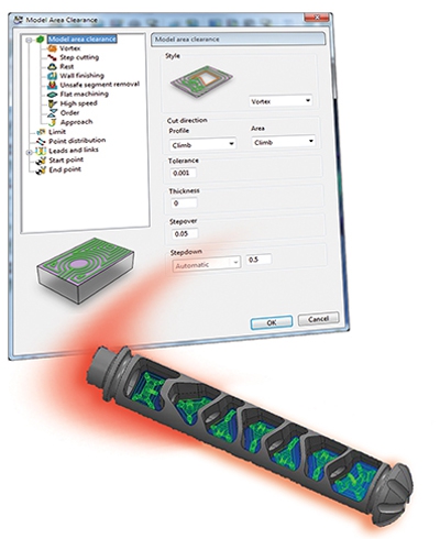
Delcam's PartMaker Inc. Division has released PartMaker 2014, which marks the introduction of Delcam's Vortex high-efficiency strategy for area clearance into the PartMaker CAM suite. Other enhancements in the 2014 version include improved back-turning and 2D pocketing functionality, support for additional tool types, faster programming of lead-in and lead-out moves and a new NC program viewer among other improvements.
Vortex is Delcam's newest proprietary high-speed roughing technology. Vortex controls the maximum engagement angle of the cutter in the material, such that the angle calculated for the programmed stepover is never exceeded, even in internal corners. This allows for optimal cutting conditions to be maintained throughout the toolpath.
By controlling the maximum engagement angle and the load on the tool, Vortex can take deeper cuts than traditionally used in roughing operations. Depths of cut up to the full flute length enable maximum material removal rate from solid carbide tooling and reduce machining times by up to 70 percent. Vortex is available as a free upgrade to licensees of PartMaker's Advanced Surface Machining (ASM) module that are on maintenance.
PartMaker 2014 includes improved functionality to support the automated programming of back-turning tools. These tools are used across a wide variety of small-part turning applications, particularly in Swiss machining. With their unique geometry and cutting characteristics, back-turning tools can eliminate the need for multiple tools and so can reduce cycle time and improve surface finish.
However, given the multiple included angles and programmable radii found on these tools, they can present toolpath calculation challenges. PartMaker 2014 overcomes these challenges with a unique, proprietary method for automating programming with back-turning tools on both the inside and outside diameter of turned parts.
Another area that has been improved is 2D pocketing. This more powerful functionality allows for more efficient and intelligent material removal from 2D pockets. The raster finishing strategy in PartMaker ASM has also been enhanced, resulting in less fragmented toolpaths without overlaps when machining highly complex shapes, thus improving part surface finish. Removing overlaps also has the added benefit of reducing cycle time by preventing over-machining of parts and by minimising lifting of the tool.
PartMaker 2014 lets users enter lead-in and lead-out moves faster than ever before for both turning and milling operations. The lead-in and lead-out dialogs have been combined into one form where values can automatically be copied from lead-in moves to lead-out moves, or vice versa. This productivity enhancement speeds up programming, reduces mouse clicks and decreases the chance of making an error.
The NC Program Viewer function allows improved analysis of the NC code generated by PartMaker to help achieve optimum productivity from the machine. It includes unique functionality for automatically aligning "wait" or "sync" codes for multi-channel machines. By simply clicking the "Align Wait/Queue Commands" button, the user can quickly see which processes are being executed simultaneously across a multi-channel CNC program and so identify opportunities for a more efficient sequence of operations. This functionality can be applied automatically to a broad spectrum of combinations of machine controls with multi-axis turn-mill machines and Swiss-type lathes.
PartMaker's extensive tool database now includes explicit selections for tapered end-mills as well as neutral turning tools and back-turning tools. Additionally, the software now automatically gives users the choice to choose between a flat-bottom, bull-nose or ball-nose end-mill when creating a new end-mill. The use of back-turning tools and tapered end-mills is available as a free upgrade to maintained licensees of PartMaker's Advanced Tools option.
Contact Details
Related Glossary Terms
- clearance
clearance
Space provided behind a tool’s land or relief to prevent rubbing and subsequent premature deterioration of the tool. See land; relief.
- computer numerical control ( CNC)
computer numerical control ( CNC)
Microprocessor-based controller dedicated to a machine tool that permits the creation or modification of parts. Programmed numerical control activates the machine’s servos and spindle drives and controls the various machining operations. See DNC, direct numerical control; NC, numerical control.
- computer-aided manufacturing ( CAM)
computer-aided manufacturing ( CAM)
Use of computers to control machining and manufacturing processes.
- gang cutting ( milling)
gang cutting ( milling)
Machining with several cutters mounted on a single arbor, generally for simultaneous cutting.
- milling
milling
Machining operation in which metal or other material is removed by applying power to a rotating cutter. In vertical milling, the cutting tool is mounted vertically on the spindle. In horizontal milling, the cutting tool is mounted horizontally, either directly on the spindle or on an arbor. Horizontal milling is further broken down into conventional milling, where the cutter rotates opposite the direction of feed, or “up” into the workpiece; and climb milling, where the cutter rotates in the direction of feed, or “down” into the workpiece. Milling operations include plane or surface milling, endmilling, facemilling, angle milling, form milling and profiling.
- numerical control ( NC)
numerical control ( NC)
Any controlled equipment that allows an operator to program its movement by entering a series of coded numbers and symbols. See CNC, computer numerical control; DNC, direct numerical control.
- toolpath( cutter path)
toolpath( cutter path)
2-D or 3-D path generated by program code or a CAM system and followed by tool when machining a part.
- turning
turning
Workpiece is held in a chuck, mounted on a face plate or secured between centers and rotated while a cutting tool, normally a single-point tool, is fed into it along its periphery or across its end or face. Takes the form of straight turning (cutting along the periphery of the workpiece); taper turning (creating a taper); step turning (turning different-size diameters on the same work); chamfering (beveling an edge or shoulder); facing (cutting on an end); turning threads (usually external but can be internal); roughing (high-volume metal removal); and finishing (final light cuts). Performed on lathes, turning centers, chucking machines, automatic screw machines and similar machines.


