PartMaker Inc. will begin shipping PartMaker Version 2013, the latest version of PartMaker Software for programming CNC Mills, Lathes, WireEDM, Turn-Mill Centers and Swiss-type lathes in the fourth quarter of 2012. Among a number of other enhancements, this new version will feature a totally revamped surface machining module offering PartMaker users some of the most powerful CAM machining algorithms on the market today for 3, 4 and 5 axis simultaneous milling operations on a variety of machining platforms including CNC Mills, Turn-Mill Centers, Bar-Fed Mills and Swiss-type lathes. PartMaker 2013 also features a restyled, more productive user interface.
"PartMaker's new Advanced Surface Machining (ASM) functionality is based on the same technology and algorithms underpinning Delcam's PowerMILL," says PartMaker Inc. division President Hanan Fishman. "The new functionality being offered in PartMaker's ASM answers the needs of our customers making ever increasingly more complicated parts, particularly for those in the medical device and aerospace arena. Also, machine tools are becoming more complex, with 5-axis simultaneous milling now even becoming available on a number of Swiss-type lathes."
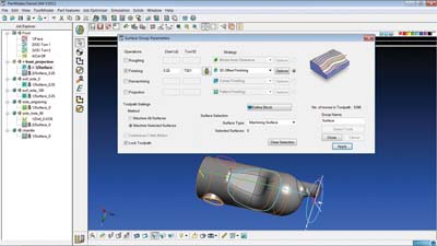
PartMaker Version 2013 features a sleeker, restyled user interface. Headlining the improvements in the user interface in PartMaker 2013 is the Job Explorer tree which makes navigating Machining Function Face Windows and Part Features faster. Additionally, a number of new controls have been added to the software to make working even more intuitive. Also, a number of diagrams in the software have been recast and revamped to give PartMaker 2013 a fresh new look.
While the user interface enhancements are numerous, PartMaker 2013 has retained the software's traditional work flow with its industry leading ease of use so existing users will not have to worry about any relearning, they will just be able to be more productive. The new high-end milling functionality available in PartMaker Version 2013 will be known as the Advanced Surface Machining module, or ASM for short. ASM will replace PartMaker's Surface Machining Wizard (SMW) module for three, four and five axis machining. For existing PartMaker users, the upgrade to ASM will be provided free of cost and the transition will be very easy to make. The benefits of the ASM module for PartMaker users are numerous. The will allow for faster tool path calculation, greater tool control and improved surface finishes, among other benefits. The ASM module will feature a wide variety of high-end milling strategies that can be applied across the entire suite of PartMaker CAM applications including PartMaker Mill, PartMaker Turn-Mill and PartMaker SwissCAM. The powerful surface machining strategies in ASM are the same as those found in PowerMILL, Delcam's CAM system for the manufacture of complex shapes. Each strategy provides for full tool control enabling them to be used in either traditional 3-axis methods or up to 5-axis simultaneous machining methods, depending on a machine tool's capability.
The advent of ASM extends PartMaker's 5-axis simultaneous milling functionality to CNC milling centers, making PartMaker an unsurpassed solution for production oriented manufacturers to solve all of their CNC programming challenges, Milling, Turning, Wire EDM, Turn-Mill and Swiss with one, unified programming platform.
PartMaker 2013 will feature Delcam's new Vortex High Speed Machining Strategies (as part of ASM). The Vortex area-clearance strategy, for which Delcam has a patent pending, has been developed by Delcam specifically to gain the maximum benefit from solid carbide tooling, in particular those designs that can give deeper cuts by using the full flute length as the cutting surface. It can be used for 2.5 and 3-axis roughing, 3+2-axis area clearance and for rest machining. Like other Delcam roughing strategies, Vortex toolpaths are calculated to give more efficient machining by following the shape of the part and by keeping air moves to a minimum. This is particularly important for rest machining operations. One fundamental problem with conventional area-clearance strategies is that the optimum cutting conditions only occur during a straight-line cut. Any internal corners within the model significantly increase the engagement angle of the cutter. To protect the cutter, this increase needs to be balanced by setting a lower feed rate. The user then has the choice of using this lower rate over the whole toolpath, which increases the machining time, or varying the feeds and speeds as the cutter moves around the model and so increasing wear on the cutter.
Unlike other high-speed roughing techniques that aim to maintain a constant theoretical metal-removal rate, the Vortex strategy produces toolpaths with a controlled engagement angle for the complete operation. This maintains the optimum cutting conditions for the entire toolpath that would normally be possible only for the straight-line moves. As a result, the cutting time will be shorter, while cutting will be undertaken at a more consistent volume-removal rate and feed rate, so protecting the machine.
Because Vortex toolpaths have a controlled engagement angle, tools will never be overloaded and so will achieve the maximum tool life. Shock loading caused by changes in the contact angle is minimized, preventing chipping of the flutes. In addition, the stability of the cutting conditions gives more consistent edge temperatures, so prolonging the life of the tool coating and removing heat damage to the surface of the part. Finally, the ability to use stepdowns of up to two, or even three times, the tool diameter spreads the tool wear evenly over the cutting surface of the tool, again contributing to longer tool life.
Contact Details
Related Glossary Terms
- centers
centers
Cone-shaped pins that support a workpiece by one or two ends during machining. The centers fit into holes drilled in the workpiece ends. Centers that turn with the workpiece are called “live” centers; those that do not are called “dead” centers.
- clearance
clearance
Space provided behind a tool’s land or relief to prevent rubbing and subsequent premature deterioration of the tool. See land; relief.
- computer numerical control ( CNC)
computer numerical control ( CNC)
Microprocessor-based controller dedicated to a machine tool that permits the creation or modification of parts. Programmed numerical control activates the machine’s servos and spindle drives and controls the various machining operations. See DNC, direct numerical control; NC, numerical control.
- computer-aided manufacturing ( CAM)
computer-aided manufacturing ( CAM)
Use of computers to control machining and manufacturing processes.
- electrical-discharge machining ( EDM)
electrical-discharge machining ( EDM)
Process that vaporizes conductive materials by controlled application of pulsed electrical current that flows between a workpiece and electrode (tool) in a dielectric fluid. Permits machining shapes to tight accuracies without the internal stresses conventional machining often generates. Useful in diemaking.
- feed
feed
Rate of change of position of the tool as a whole, relative to the workpiece while cutting.
- flutes
flutes
Grooves and spaces in the body of a tool that permit chip removal from, and cutting-fluid application to, the point of cut.
- gang cutting ( milling)
gang cutting ( milling)
Machining with several cutters mounted on a single arbor, generally for simultaneous cutting.
- metal-removal rate
metal-removal rate
Rate at which metal is removed from an unfinished part, measured in cubic inches or cubic centimeters per minute.
- milling
milling
Machining operation in which metal or other material is removed by applying power to a rotating cutter. In vertical milling, the cutting tool is mounted vertically on the spindle. In horizontal milling, the cutting tool is mounted horizontally, either directly on the spindle or on an arbor. Horizontal milling is further broken down into conventional milling, where the cutter rotates opposite the direction of feed, or “up” into the workpiece; and climb milling, where the cutter rotates in the direction of feed, or “down” into the workpiece. Milling operations include plane or surface milling, endmilling, facemilling, angle milling, form milling and profiling.
- milling machine ( mill)
milling machine ( mill)
Runs endmills and arbor-mounted milling cutters. Features include a head with a spindle that drives the cutters; a column, knee and table that provide motion in the three Cartesian axes; and a base that supports the components and houses the cutting-fluid pump and reservoir. The work is mounted on the table and fed into the rotating cutter or endmill to accomplish the milling steps; vertical milling machines also feed endmills into the work by means of a spindle-mounted quill. Models range from small manual machines to big bed-type and duplex mills. All take one of three basic forms: vertical, horizontal or convertible horizontal/vertical. Vertical machines may be knee-type (the table is mounted on a knee that can be elevated) or bed-type (the table is securely supported and only moves horizontally). In general, horizontal machines are bigger and more powerful, while vertical machines are lighter but more versatile and easier to set up and operate.
- shock loading
shock loading
Tool is subjected to sudden, heavy loads and/or impacts, as in interrupted cutting. See interrupted cut.
- toolpath( cutter path)
toolpath( cutter path)
2-D or 3-D path generated by program code or a CAM system and followed by tool when machining a part.
- turning
turning
Workpiece is held in a chuck, mounted on a face plate or secured between centers and rotated while a cutting tool, normally a single-point tool, is fed into it along its periphery or across its end or face. Takes the form of straight turning (cutting along the periphery of the workpiece); taper turning (creating a taper); step turning (turning different-size diameters on the same work); chamfering (beveling an edge or shoulder); facing (cutting on an end); turning threads (usually external but can be internal); roughing (high-volume metal removal); and finishing (final light cuts). Performed on lathes, turning centers, chucking machines, automatic screw machines and similar machines.
- wire EDM
wire EDM
Process similar to ram electrical-discharge machining except a small-diameter copper or brass wire is used as a traveling electrode. Usually used in conjunction with a CNC and only works when a part is to be cut completely through. A common analogy is wire electrical-discharge machining is like an ultraprecise, electrical, contour-sawing operation.