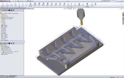
Geometric Technologies Inc. has announced the release of CAMWorks 2011, the latest version of its solid-based CNC programming solution.
CAMWorks 2011 is intended to be a more focused upgrade in the CAMWorks line and provide significant new capabilities including enhanced automation, improved knowledge-based machining information, smarter toolpaths, and more.
CAMWorks 2011 introduces VoluMill the ultra high-performance toolpath plug-in engine for high speed milling for 2.5 axis and 3 axis roughing operations. It is ideal for prismatic parts and complex 3-D shapes as its algorithms result in more intelligent toolpaths to machine pockets, slots, and arbitrary shapes. It can be used with any material, including the hardest metals. The result is increased efficiency and utilization of machines, tools, labor and materials.
For the mold and die industry, Geometric has introduced an optional electrode design solution labeled ElectrodeWorks that automates all aspects of the calculation and design of EDM electrodes including design, management, documentation and manufacturing. Its seamless integration with SolidWorks/CAMWorksSolids assures complete parametric association of data, according to the company.
Feature Recognition, which is used to automatically identify areas to be machined, has been upgraded to find more features, while decreasing computation times by more than 50 percent over previous CAMWorks versions. As part models become increasingly complex, recognizing more features in less time represents huge time savings for the NC programmer. The proprietary Technology Database (TechDB) that is used to store and apply knowledge based machining information, has been enhanced to simplify the process of creating best machining practices. The improved interaction will result in greater use of the knowledge-based machining capabilities of CAMWorks, and will reduce potential errors in machining information. Additional enhancements with CAMWorks 2011 include improved performance and enhanced feature recognition of slot features with fillet and taper as well as slots with islands.
Users can now define customized turn inserts when it is not possible to completely machine a turn part using a standard turn insert line diamond, square, etc. Such custom turn inserts can be defined for inner as well as outer diameter. And while earlier versions of CAMWorks did not provide flexibility to define work-in-process for turning operations, CAMWorks 2011 provides the user with the option to define the operation to be considered as the work-in-process within the entire operation.
Contact Details
Related Glossary Terms
- 3-D
3-D
Way of displaying real-world objects in a natural way by showing depth, height and width. This system uses the X, Y and Z axes.
- computer numerical control ( CNC)
computer numerical control ( CNC)
Microprocessor-based controller dedicated to a machine tool that permits the creation or modification of parts. Programmed numerical control activates the machine’s servos and spindle drives and controls the various machining operations. See DNC, direct numerical control; NC, numerical control.
- electrical-discharge machining ( EDM)
electrical-discharge machining ( EDM)
Process that vaporizes conductive materials by controlled application of pulsed electrical current that flows between a workpiece and electrode (tool) in a dielectric fluid. Permits machining shapes to tight accuracies without the internal stresses conventional machining often generates. Useful in diemaking.
- fillet
fillet
Rounded corner or arc that blends together two intersecting curves or lines. In three dimensions, a fillet surface is a transition surface that blends together two surfaces.
- gang cutting ( milling)
gang cutting ( milling)
Machining with several cutters mounted on a single arbor, generally for simultaneous cutting.
- milling
milling
Machining operation in which metal or other material is removed by applying power to a rotating cutter. In vertical milling, the cutting tool is mounted vertically on the spindle. In horizontal milling, the cutting tool is mounted horizontally, either directly on the spindle or on an arbor. Horizontal milling is further broken down into conventional milling, where the cutter rotates opposite the direction of feed, or “up” into the workpiece; and climb milling, where the cutter rotates in the direction of feed, or “down” into the workpiece. Milling operations include plane or surface milling, endmilling, facemilling, angle milling, form milling and profiling.
- numerical control ( NC)
numerical control ( NC)
Any controlled equipment that allows an operator to program its movement by entering a series of coded numbers and symbols. See CNC, computer numerical control; DNC, direct numerical control.
- outer diameter ( OD)
outer diameter ( OD)
Dimension that defines the exterior diameter of a cylindrical or round part. See ID, inner diameter.
- toolpath( cutter path)
toolpath( cutter path)
2-D or 3-D path generated by program code or a CAM system and followed by tool when machining a part.
- turning
turning
Workpiece is held in a chuck, mounted on a face plate or secured between centers and rotated while a cutting tool, normally a single-point tool, is fed into it along its periphery or across its end or face. Takes the form of straight turning (cutting along the periphery of the workpiece); taper turning (creating a taper); step turning (turning different-size diameters on the same work); chamfering (beveling an edge or shoulder); facing (cutting on an end); turning threads (usually external but can be internal); roughing (high-volume metal removal); and finishing (final light cuts). Performed on lathes, turning centers, chucking machines, automatic screw machines and similar machines.


