How Bombardier Transportation uses tool management to keep production on track.
The heart of rail technology beats in Germany, where the Bombardier Transportation division of the Canadian conglomerate is headquartered in Berlin. Its plant in Netphen, Germany, annually produces 2,500 to 3,000 carriage bodies and bogies (a chassis or framework with wheels that is attached to a railway vehicle). This equipment is used in vehicles ranging from trams to high-speed trains. Despite the European economic crisis, order volumes have risen over the last few years, to the point where the plant, which has a workforce of 700, is nearly at full capacity.
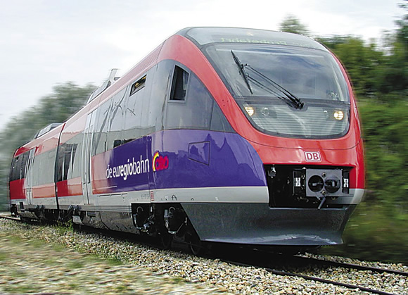
Courtesy of Bombardier Transportation
Bombardier Transportation is the world’s largest manufacturer of rail transport vehicles.
To meet growing demand, the company realized it needed to improve productivity and reduce the downtime required to tool and retool its machine tools and load new NC programs. As a result, it installed a Zoller Tool Management Solutions (TMS) system to access actual cutting tool data during 3-D CAM programming.
Stopping the Errors
Prior to incorporating TMS, CAM programmers were producing NC programs for machining bogies using a 2½-D CAM system, which was time-consuming and error-prone, according to Michael Kringe, the company’s applications specialist. “We programmed from 2-D drawings, which meant we never really knew what the chassis looked like and if we had properly taken into account how to machine all of the interference edges,” he said.
In addition, the CAM programmers could only specify tools to a certain extent in advance because they had no direct access to the information in the old Microsoft Access tool database. That meant additional work for toolsetting personnel, who had to compile complete tools (cutting tools and holders) based on an approximate tool list and drawings. In many instances, tools were found to be slightly too short or too long only when the NC programs were initially run, requiring further retooling.
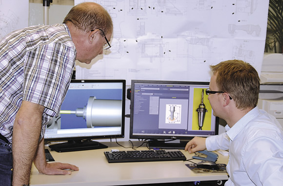
Courtesy of Michael Wendenburg/Zoller
Michael Kringe (left), applications specialist, and Damian Sakwerda, CAM programmer, access tool data during CAM programming at Bombardier Transportation via the integrated Zoller tool management system.
A new tool management system not only had to support CAM programming, it also needed to assist with the administration of tool inventory and storage locations, as well as the ordering system. And it had to be able to communicate with the tool measuring equipment.
“We wanted a solution from a single source,” said Damian Sakwerda, a CAM programmer. “Because we had already been working with a Zoller presetter, we decided to purchase a new Zoller smile 600/CNC and invest in the Zoller Tool Management Solutions system.”
Single Source
According to Zoller Inc., Ann Arbor, Mich., the main advantage of TMS is it enables users to have one source for all tool data instead of several databases. Also, because the presetter is integrated into TMS, users can record actual tool measurements. This is beneficial primarily because diameters and lengths can vary as tools are reground, and since tools are measured again after being reground, the database contains all the information it needs to support accurate machining. This saves times and minimizes errors when selecting tools.
The Netphen plant has about 2,500 complete tools in circulation, with 1,200 of those just for its four Bimatec Soraluce drill/mill centers. Those tools can be moved from inventory to presetting, into buffer storage and magazines and then to the machine tools—and may get swapped out several times in between. Because TMS is aware of the tools’ respective storage locations, time-consuming searches for tools are eliminated, leading to enhanced availability and reduced inventory requirements. Kringe estimates that the Zoller TMS reduces annual tool costs by 25 percent, a savings of about $64,000.
Selecting a CAM System
When Bombardier Transportation was selecting a 3-D CAM package to integrate with TMS, four made the final cut and were tested against each other using an identical workpiece. The evaluation team’s final selection was TopSolid’Cam from Evry, France-based Missler Software, which has a U.S. subsidiary in Addison, Ill. It was selected because of its ease of use, comprehensive range of import functions and preparation of 3-D CAM models from third-party systems.
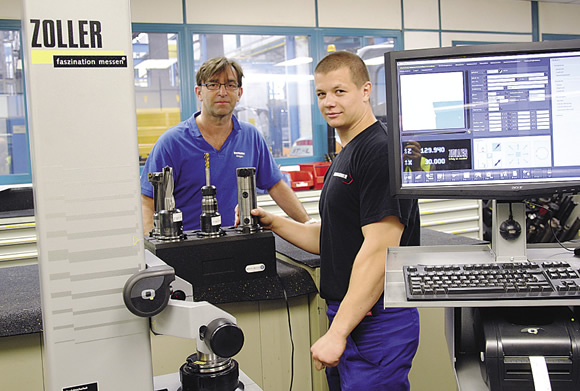
Courtesy of Michael Wendenburg/Zoller
Rüdiger Hof (left) and Sergej Ponoma-Renko from Bombardier Transportation’s setting department preset tools with the Zoller smile 600/CNC presetter.
TopSolid’CAM value-added reseller Moldtech GmbH, Salzkotten, Germany, installed the workstations and, working with Zoller, programmed the bidirectional interface between the CAM system and TMS. CAM programmers key their desired characteristics and properties into TopSolid’Cam and gain direct access to the tool data in TMS, simplifying their work and improving the reliability of the NC programs.
To use the tool data to simulate CAM programming, 3-D models are required. These models are usually created from article characteristics as bounding geometry and made available to the CAM system. However, when the tools have complex contours, they can also be generated manually and stored in the tool database. Another option is importing 3-D models from manufacturers’ catalogs in neutral formats. The list of tools used for NC programming can then be sent back to TMS, which generates setting sheets (lists containing the tool assemblies required for a specific job), reducing the need for adjustments.
Moldtech also implemented TMS in the plant’s machinery, which was challenging for the complex Bimatec Soraluce machines because they have indexing turrets and tool-changing heads (tools are fixed in indexing turrets, while tool-changing heads use quick-change tooling). Depending on which surfaces of a chassis require machining, the tools can be in a fixed head, an angle head or a pivot-orthogonal head.
Because machining with the CAM software is programmed in a virtual machine environment, the kinematics of the indexing turrets must be reliably simulated with their degrees of freedom and accurately translated into machine language. Moldtech provided the kinematically prepared machine models and post-processor.
Bombardier Transportation has standardized operations on its various drill/mill machine tools to such an extent that it only requires one post-processor. Adapting and optimizing the post-processor required a fair amount of work because Moldtech not only had to simulate machine-specific functions but also had to depict company-specific machining cycles.
This has led to operational improvements. For example, CAM programmers use a subroutine technique within the new environment. “An operation such as milling, line-by-line milling or trimming can be set up just once as a subroutine, which is then called up several times at different feed depths,” Sakwerda said. This means NC programs can be relatively lean, which makes them easier to produce and work with.
Take a Position
Milling and drilling a complete welding frame can take 22 hours, depending on the complexity. Kringe estimated that setup times for machining a new workpiece, including tool assemblies and programming times, have been cut by 50 percent. The simulation functions in the CAM software allow programmers to detect possible collisions while still only working on the computer, enhancing worker safety and operational reliability. Furthermore, the time it takes for a tool to go from inventory to a machine tool can be simulated and optimized.
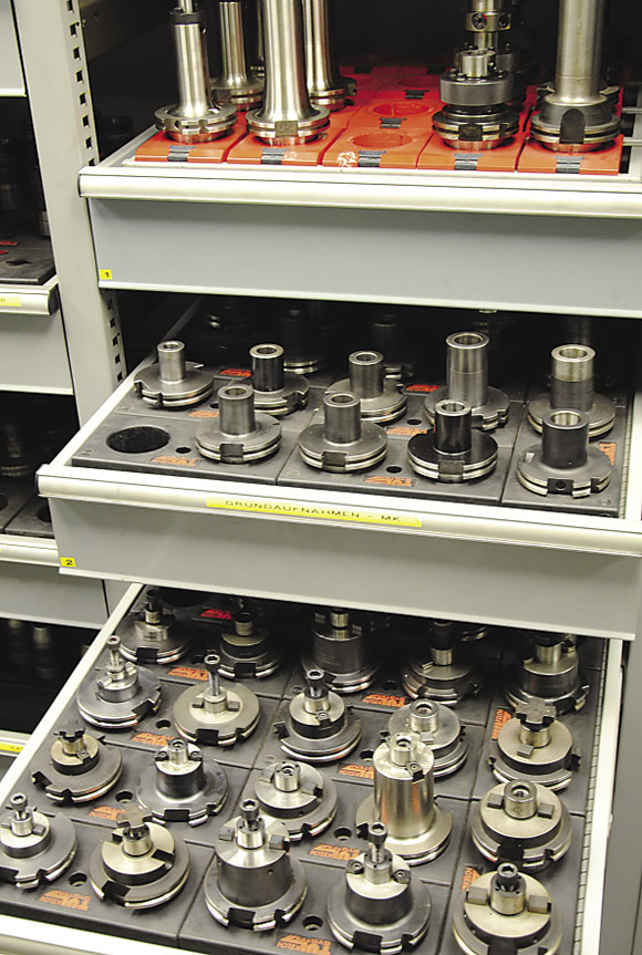
Courtesy of Michael Wendenburg/Zoller
A selection of tools at Bombardier Transportation.
Bombardier Transportation has cut the time to tool and retool a machine because TMS knows which tools are already available on each machine. This allows the company to reduce the time to implement machining of a defined workpiece on a different machine tool from 4 to 5 hours to 2 to 3 hours.
“Thanks to 3-D programming and integrated tool management, we have become substantially more productive in our machining operations,” Sakwerda said.
Rüdiger Hof from the toolsetting department added, “We can work in a much more relaxed way because, thanks to the Zoller TMS, errors have pretty much stopped occurring.” CTE
Related Glossary Terms
- 2-D
2-D
Way of displaying real-world objects on a flat surface, showing only height and width. This system uses only the X and Y axes.
- 3-D
3-D
Way of displaying real-world objects in a natural way by showing depth, height and width. This system uses the X, Y and Z axes.
- arbor
arbor
Shaft used for rotary support in machining applications. In grinding, the spindle for mounting the wheel; in milling and other cutting operations, the shaft for mounting the cutter.
- centers
centers
Cone-shaped pins that support a workpiece by one or two ends during machining. The centers fit into holes drilled in the workpiece ends. Centers that turn with the workpiece are called “live” centers; those that do not are called “dead” centers.
- computer-aided manufacturing ( CAM)
computer-aided manufacturing ( CAM)
Use of computers to control machining and manufacturing processes.
- degrees of freedom
degrees of freedom
Number of axes along which a robot, and thus the object it is holding, can be manipulated. Most robots are capable of maneuvering along the three basic Cartesian axes (X, Y, Z). More sophisticated models may move in six or more axes. See axis.
- feed
feed
Rate of change of position of the tool as a whole, relative to the workpiece while cutting.
- gang cutting ( milling)
gang cutting ( milling)
Machining with several cutters mounted on a single arbor, generally for simultaneous cutting.
- milling
milling
Machining operation in which metal or other material is removed by applying power to a rotating cutter. In vertical milling, the cutting tool is mounted vertically on the spindle. In horizontal milling, the cutting tool is mounted horizontally, either directly on the spindle or on an arbor. Horizontal milling is further broken down into conventional milling, where the cutter rotates opposite the direction of feed, or “up” into the workpiece; and climb milling, where the cutter rotates in the direction of feed, or “down” into the workpiece. Milling operations include plane or surface milling, endmilling, facemilling, angle milling, form milling and profiling.
- numerical control ( NC)
numerical control ( NC)
Any controlled equipment that allows an operator to program its movement by entering a series of coded numbers and symbols. See CNC, computer numerical control; DNC, direct numerical control.