If drawings of the same multiaxis part were given to five different CNC programmers, chances are they would come up with five different machining methods. This variability is a product of the programmer’s experience, part quantities and available multiaxis equipment, CAD/CAM systems, tooling, fixturing and materials.
What do all CNC programmers do when asked to write a program for a new part? They create a mental image of the part and, based on the above factors, go through various scenarios to determine how to machine it. These include how to hold the part and which side to start on. Programmers then mentally go through the process of removing excess material from the starting stock to free the desired part from the workpiece. Most programmers brainstorm the same part repeatedly and develop multiple solutions. They add new ideas, eliminate the weakest ones and then make the final decision. This process happens long before the toolpath is created.
This prework “meditation” is the single most important part of the entire manufacturing process.
The process described here is the same regardless of the number of axes involved. The big difference typically involves fixturing. What workholding to use is among the first decisions to be made when programming a 3-axis machine. Many 4- and 5-axis (multiaxis) programmers will place the part data on a virtual machine. This process lets them “levitate” the part and simulate the machine’s motions without a fixture present to see if all motions are possible without violating the machine’s work envelope. The part is moved in space to achieve optimized, synchronized motion. Final fixture placement or design might be one of the last steps.
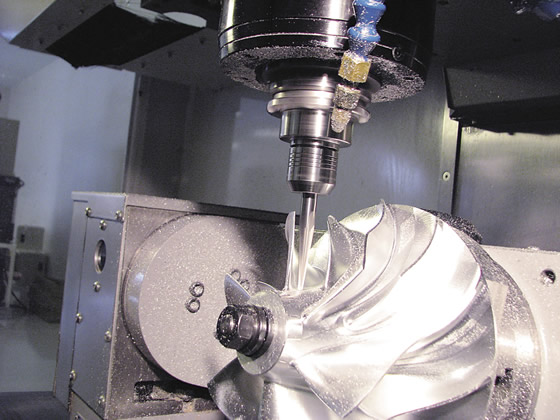
Courtesy of CNC Software
When making a cutting tool list for a job, start by diligently analyzing the part geometry.
Of course, this procedure is not always possible, but when a fixture is predetermined, additional effort is required to ensure there will be no collisions involving the fixture, tool, shank, arbor or toolholder. Avoiding collisions is a big part of multiaxis programming. Collisions can occur not only during cutting, but also during tool changes, pallet changes or manual retraction moves after an abrupt program stop. For example, after a power failure, the cutting tool could be in a position where the only safe retraction move is simultaneous, multiaxis motion.
The single most important part of multiaxis programming is the initial time spent on deciding how to tackle the job. Machining sequences should be kept simple and not made complicated just because the shop has the latest equipment, the most powerful CAD/CAM system or an unlimited budget. The following are some questions that must be answered.
■ How many parts are needed?
■ How much time is available?
■ What is the workpiece material?
■ What machine is available?
■ How good is the CAD/CAM system?
■ How much is known about CAD/CAM?
■ What tooling is available?
■ Are existing fixtures available or do new ones need to be made?
■ Are there any special requirements?
Limitations apply to every piece of equipment in a shop. The trick is to work around those limitations. The difference between a good multiaxis programmer and an average one is that the good one is industrious. If one machining approach doesn’t work, another one will be tried until the best solution is revealed.
In the long run, preparing the work will be time well spent. Once a decision has been made about how the job will be handled, the work must be organized. Divide up the operations in the CAD/CAM system and move necessary geometry to easily recognizable named layers and levels. This preparation helps isolate individual features and enables a focused work flow.
Make a cutting tool list for any job. Start by diligently analyzing the part geometry. Find the smallest fillets. Measure how much room there is between features to determine the minimum and maximum tool diameters that can be used. Check to see which tools are available in the shop to determine if any of them can be applied, especially if you are already familiar with their performance. If you must order tools, research their performance and availability.
Check on available fixtures, vises and clamps. Use existing vises and fixtures whenever possible to control costs. The equipment should be modeled in the CAD/CAM system and organized into libraries so it can be readily accessed and loaded for virtual simulation when checking for possible collisions.
If more than one machine is available for the job, compare them. Among the essential checks are: work envelope limitations, maximum rpm, available feed rates and controller capabilities.
Material stocks must also be considered. If the material is unfamiliar, research its cutting characteristics. The original form may be a billet, cylinder, casting or forging, and may require some preparatory work before machining can start. CTE
Related Glossary Terms
- arbor
arbor
Shaft used for rotary support in machining applications. In grinding, the spindle for mounting the wheel; in milling and other cutting operations, the shaft for mounting the cutter.
- computer numerical control ( CNC)
computer numerical control ( CNC)
Microprocessor-based controller dedicated to a machine tool that permits the creation or modification of parts. Programmed numerical control activates the machine’s servos and spindle drives and controls the various machining operations. See DNC, direct numerical control; NC, numerical control.
- feed
feed
Rate of change of position of the tool as a whole, relative to the workpiece while cutting.
- fixture
fixture
Device, often made in-house, that holds a specific workpiece. See jig; modular fixturing.
- shank
shank
Main body of a tool; the portion of a drill or similar end-held tool that fits into a collet, chuck or similar mounting device.
- toolholder
toolholder
Secures a cutting tool during a machining operation. Basic types include block, cartridge, chuck, collet, fixed, modular, quick-change and rotating.
- toolpath( cutter path)
toolpath( cutter path)
2-D or 3-D path generated by program code or a CAM system and followed by tool when machining a part.
- work envelope
work envelope
Cube, sphere, cylinder or other physical space within which the cutting tool is capable of reaching.


