Part manufacturers must continually increase productivity without sacrificing quality. Several new integrated digital solutions have emerged that support this process.
The demand for integrated, connected manufacturing systems is growing. Shorter product life cycles put pressure on manufacturing engineers and machinists to decrease the time from part design to production while keeping on top of advances in equipment and tools, such as the use of multitask tools that can perform complex operations simultaneously. As the metalworking industry shifts from mass production to mass customization, companies are asking their CAM software to enable more rapid, adaptable and accurate production via machining simulation.
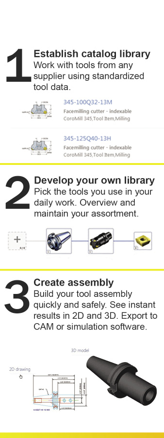
Courtesy of Sandvik Coromant
Three steps to higher productivity and security when CAM programming.
When using CAM for simulation, operators must populate the virtual tool libraries that are part of many CAM programs. This is a time-consuming process that they must re- create at the start of each new project. A problem is the lack of standardized data among different brands of tools, requiring more effort to interpret data from various cutting tool catalogs in different formats and to communicate with various shop floor devices. Sometimes, the lack of standardization can lead to unpredictable results.
Several solutions have emerged which, when applied cooperatively, offer an intelligent, comprehensive and integrated solution.
Standardized Tool Data
There are approximately 1.2 million manufacturing units in the world. Traditionally, all CAM suppliers, machine tool builders and toolmakers developed their own methods of denominating and structuring tool information. The need for a standard way of communicating tool data is apparent to anyone who searches for and maps cutting tool data as part of a project design.
Enter ISO 13399, an international standard for describing tool data. ISO 13399 describes how attributes of each tool, such as length, width and radius, are to be defined, allowing cutting tool data to be consistent regardless of the manufacturer or brand. When all tools share the same parameters and definitions, the communication of tool information between software systems and machines improves considerably. Some cutting tool manufacturers, such as Sandvik Coromant AB, Sandviken, Sweden, are using the standard. Several other large cutting tool suppliers are in the process of moving data to the ISO 13399 format.
Tool Data Libraries
CAM operators typically search for tool data in different catalogs and Web sites each time they begin a project. They have no way of saving their most-often-used tools in a personal collection or database. A virtual library of the available tools provides a solution. One such tool library is Adveon, developed by Sandvik Coromant. It is an open-platform library on which any cutting tool supplier can load its ISO 13399-compliant catalogs. Sandvik Coromant’s initial contribution, already available in Adveon, includes about 12,000 tools within its rotational assortment.
The library enables subscribed users to quickly make updates, additions and corrections, providing them up-to-date data. Plans for adding modules to Adveon to support tool recommendations for process optimization are in the works.
“Companies can no longer afford to rely on manual data entry, and operators need a single tool library that can manage tools from multiple manufacturers,” said Klas Forsström, president of Sandvik Coromant AB. “Adveon has been designed to address these challenges.”
Integrated Solutions
The availability of a comprehensive library of standardized tool data helps enable toolpath simulation. The next step is to embed the library into CAM programs. Once a tool library is integrated into CAM software—including simulation modules—planning and selecting tools is optimized. This makes computer modeling of the manufacturing process easier.
With an embedded tool library, the CAM operator can search for components and receive options from the library. Once he makes appropriate selections, part assemblies can be quickly built in 2D drawings and 3D models, which can then be exported to simulation modules. The entire process reduces the time spent on tool selection and tool assembly, enabling more precise simulations.
CAM software integrated with an ISO 13399-compliant tool library improves the consistency and quality of data. A library loaded with standardized information presents only the most dependable options and designs. Accurate tool data increases confidence in the manufacturing process, while accurate simulation in the CAM environment and visualization of virtual machining reduces the likelihood of collisions when machining.
This is critical when working with difficult-to-machine metals. The density and resistance of these materials makes it especially important for users to determine optimal toolpaths. Predicting and accounting for the wear pattern of each tool when machining different types of metal is a vital aspect of production design, and an integrated tool library can help make that possible.
The progress toward integrating tool libraries and CAM software is well underway. Edgecam, from CAM developer Vero UK Ltd., Berkshire, England, was the first to integrate Adveon into CAM, and was joined in July by Gibbs and Associates, Moorpark, Calif., developer of GibbsCAM software. Other CAM developers are planning to integrate Adveon as well.
The system allows CAM users to create tool assemblies based on frequently repeated projects. Users can build their tool assemblies and databases, see immediate results in 2D and 3D, and export them for CAM programming and simulation—all from one platform. Tool data updates from toolmakers are made automatically to Adveon via a cloud application, so users download new tool data each time they open the tool library integrated into their CAM software.
“Our job is to go from ‘virtual component’ to ‘real component’ as quickly as possible,” said Edgecam’s General Manager Raf Lobato. “There are two key issues that we strive to resolve: The time taken to produce the NC code, and the time taken on the machine to produce the component.”
He added that several elements must be combined to do this properly. The system must allow the user to replicate the real environment in the virtual environment as closely as possible. This includes workholders, workpieces and machine tools. Also, the system should support the best possible workflow for generating and proving out the NC code, and ensure that the NC code for tooling, toolpaths and speeds and feeds are optimized to reduce cycle time.
With tool libraries integrated with CAM software, tool selection will no longer be deferred to the point when production begins on the shop floor; it can be incorporated into the part planning and design phases.
The growth of digital manufacturing strategies depends on the integration of once-disparate technologies into a seamless, predictable and cost-effective process. Digital tool information, integrated into CAM software, can improve workflow, product quality and manufacturing efficiency, ultimately leading to products that reach the market faster. CTE
Related Glossary Terms
- computer-aided manufacturing ( CAM)
computer-aided manufacturing ( CAM)
Use of computers to control machining and manufacturing processes.
- metalworking
metalworking
Any manufacturing process in which metal is processed or machined such that the workpiece is given a new shape. Broadly defined, the term includes processes such as design and layout, heat-treating, material handling and inspection.
- numerical control ( NC)
numerical control ( NC)
Any controlled equipment that allows an operator to program its movement by entering a series of coded numbers and symbols. See CNC, computer numerical control; DNC, direct numerical control.
- toolpath( cutter path)
toolpath( cutter path)
2-D or 3-D path generated by program code or a CAM system and followed by tool when machining a part.
- web
web
On a rotating tool, the portion of the tool body that joins the lands. Web is thicker at the shank end, relative to the point end, providing maximum torsional strength.
Wesley Tonks of Edgecam co-authored this report.


