When a toolpath is precisely dialed in for high-efficiency roughing (HER), the cutting tool sings a sweet song of potent productivity rather than moaning like it’s struggling for its life. “It’s not that grunting, groaning and grinding,” said Scott Tiehen about HER. “It’s like comparing a motor that is tuned up and humming well to one that has two or three cylinders not firing correctly.”
Tiehen is national sales manager for Helical Solutions Inc., Gorham, Maine, which makes high-performance cutting tools to enhance the productivity-boosting performance of software developed to generate toolpaths for HER. One such software offering is VoluMill from Celeritive Technologies Inc. “We realized the effectiveness of the VoluMill toolpath when we first saw it,” he said.
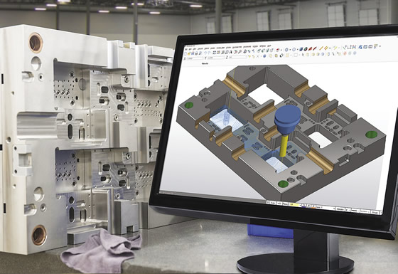
Moldmaking motion
Glenn Coleman, chief product officer for Celeritive, Moorpark, Calif., explained that CAM-system-independent VoluMill, introduced in 2008, controls the removal rate, or volume, of metal being milled at any given time so it never exceeds a user-controlled upper threshold. “What users experience is a consistent, predictable and known load on the cutting tools, machine tools and workholding components,” he said, adding that the software’s volume-based approach calculates cubic inches of material being removed by multiplying the DOC by the WOC by the ipm. “You can run speeds, feeds and depth of cuts that are considerably more aggressive than you can with traditional toolpaths, but you’re still being kinder and gentler on the cutting tools and machine tools.”
HER is particularly useful for moldmakers because they frequently rough molds with multiple cavities, some of which have deep and angled walls, and complex, freeform shapes.
In addition, moldmakers often perform hard milling and HER can be effective for that. For instance, as shown in the video that accompanies the online presentation of this article (see below), Accede Mold & Tool Co. Inc., Rochester, N.Y., initially began high-efficiency roughing using the Dynamic toolpath motion strategy generated by Mastercam CAD/CAM software, noted Robert Fackelman, CNC programmer for the moldmaker.
He added that Accede needed to produce a mold from H-13 tool steel hardened to 50 to 52 HRC for a pressing job. "We were kind of laughing because we really didn 't think it was going to work, but we were going to give it a shot. " However, no problems arose. "It kind of brought the naysayers to their knees, " Fackelman said. "It was pretty awesome. "
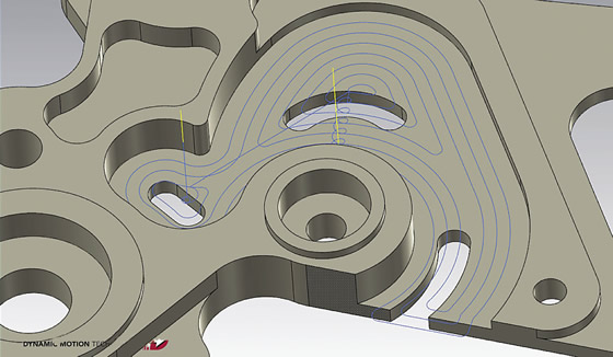
A complex mold plate, usable for a variety of different molds, made using toolpaths generated by Mastercam 's Dynamic Motion high-efficiency roughing module.
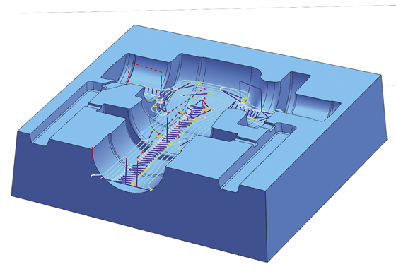
VoluMill toolpaths constantly change the motion of the cutting tool to maintain a consistent chip load, such as when moldmaking.
Breaking with Tradition
According to Coleman, the traditional approach uses parallel offset toolpaths where the CAM program repeatedly offsets the boundary of a part feature, such as a deep slot in a mold, to generate the toolpath. “That immediately introduces sharp corners into the path,” he said. “No matter what a programmer might desire as his cut width or step-over, it will always be exceeded when the tool gets into those corners.”
This scenario means cutting tools and machine tools are pushed to their limits in the corners, where cutting conditions are the worst, but are underutilized elsewhere, which reduces roughing productivity, Coleman noted.
He added that all CNC machines operate according to one principle: Do what the toolpath tells them to do. “If the toolpath tells a machine to jam that tool in the corner, that is what it’s going to do,” Coleman said. “The cutting tools are just along for the ride.”
To overcome this offset-toolpath limitation, HER software constantly changes the motion of the cutting tool to maintain a more consistent chip load while applying the entire flute length of a tool rather than just a portion, as the conventional method does, said Ben Mund, marketing for CNC Software Inc., Tolland, Conn. “You take a light-but-deep cut, which distributes heat much more effectively, and tool wear is uniform and greatly reduced.”
The developer of Mastercam CAD/CAM software created the Dynamic toolpath motion strategy to enable HER and is integrating it into its suite of milling and turning products. “A tool manufacturer will give you the maximum efficiency of a tool based on a straight cut,” Mund said. “At its simplest, Dynamic motion tries to take that ideal condition and spread it over the entire toolpath.”
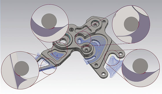
Traditional offset-based toolpaths (left) are governed by the shape of the geometry that drives them and there is little concern for or knowledge of the remaining material, engagement, chip thickness and efficiency. In contrast, high-efficiency roughing toolpaths (right), such as the ones generated by Mastercam’s Dynamic Motion, are based on maintaining the exact same chip thickness regardless of where the tool is or the material the tool is shearing.
Mund added that Dynamic motion evolved from the concept of radial chip thinning, where the goal is to produce chips as close to ideal at all times. This requires engaging as much of the tool as possible while frequently changing the engagement to ensure consistent chip load. The advantage of Dynamic motion is that once end users are satisfied with their feed rate parameters for a given material, tool and tool diameter, they can feel confident that the tools will always be kept in a safe, optimal cutting condition, regardless of part geometry.
Although some might consider HER to be similar to high-speed roughing, Mund emphasized the differences. A high-speed machine is suitable for HER, but it doesn’t require it. “One of the counterintuitive things is that a lot of folks look at Dynamic toolpaths and think they need a high-speed machine to use them; this is completely untrue,” he said, noting much of the efficiency comes from the tool motion and not the specifics of the machine. “Even someone using an old Bridgeport 3-axis machine is going to benefit from Dynamic.”
Coleman concurred that HER can extract high performance from any machine tool, but the smooth, more-controlled cutter load often makes the gains seen in small, low-horsepower, less-rigid machine tools the most impressive. “We have customers with extremely old machines that are able to run much faster on those machines to the point where they are kind of in a state of disbelief.”
The resulting tool marks from those toolpaths can seem chaotic because of the constantly changing motion. “The part is dead nuts on, but the tool marks look strange because the tool motion is so much different than what people are used to,” Mund said. This aesthetic difference means some end users, such as those in the medical industry, may not use if for all their finishing operations, but they still benefit from using it for roughing.
HEM and HER
When a machine tool lacks rigidity, such as from a long tool overhang, small spindle interface or 90° milling head, Iscar Metals Inc. offers High Efficiency Machining (HEM) as an option that correlates with enhanced toolpath-motion technology, noted Tom Raun, OEM specialist for the Arlington, Texas, toolmaker. In Mastercam, HEM integrates the CAM software package’s Dynamic toolpath motion with Iscar’s Chatterfree solid-carbide cutting tools and Iscar’s cutting parameter algorithms, which are built into the software to control cutting conditions such as rpm, feed rate and radial chip thinning.
“HEM allows you to apply a different approach to roughing where you’re still able to get a good metal-removal rate out of a not-so-rigid circumstance,” Raun said.

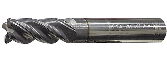
A Helical EDP 34307 (HEV-L-50500-R.030) 5-flute, ½ "-dia. endmill roughs 36-HRC TiAl6V4 at a cutting speed of 589 sfm and a feed rate of 48 ipm, a 2.0 " axial DOC and a 0.035 " radial DOC for a metal-removal rate of 3.36 in.3/min. on a Haas VF-2SS vertical machining center with a high-efficiency toolpath generated by Autodesk’s Adaptive Clearing software.
Raun added that integrating HEM with a HER toolpath-motion strategy enables an end user to drastically increase cutting speeds for most applications, as long as the machine tool can achieve that. This combination also makes tool engagement, horsepower consumption and spindle load highly consistent—“flatlining” them. “It doesn’t put a lot of stress and strain on the machine or the cutting tool when applied properly,” he said.
In addition, Iscar developed the All-In-One endmill in coordination with CNC Software (Mastercam). The tool has a high-feed geometry on the tip instead of a 90° feature to minimize tip wear during ramping entry motions, such as when milling a mold pocket, Raun explained. This balances wear on the tip and the flutes, extending tool life and avoiding tools being discarded or reground because the tool tip is worn while the rest of the tool is not.
With the proper tools being applied to follow the most-efficient toolpaths, Raun estimates part manufacturers can reduce cycle times by up to 70 percent or more, depending on the application. Although quantifying cycle time reduction and tool life extension are straightforward, he noted the impact HER has on machine tool life is not as clear cut. This is because it’s a challenge to accurately gage the effect an unwelcome event has on a machine.
“What’s the impact of a catastrophic tool failure or a crash on a spindle?” Raun asked. “You might start the machine and it seems like it is running fine, but maybe you reduced the life of your spindle or spindle bearings by a great amount. If you do that on a consistent basis, I would expect your spindle life will be drastically less than if you’re always programming with control.”
Taking a Load Off
The repair department is not going to be as busy as it used to be, but Helical’s Tiehen concurred that it is difficult to determine the exact reduction in machine tool wear and tear that occurs after switching to HER, saying, “I wish I could measure that.”
What can be measured, however, is spindle load. Tiehen pointed out that HER can help keep the spindle load less than 50 percent on a light-duty VMC even when cutting titanium, stainless steel and other “brutal” materials, which tend to cause a load meter to peg without the efficient toolpaths. “It’s not uncommon for us to experience a 20 to 30 percent spindle load while running two to four times the mrr a customer was machining at prior to employing the HER strategy,” he said.
The Chatterfree solid-carbide endmill from Iscar Metals has a variable-pitch, variable-helix design.
HER can improve the performance of just about any cutting tool, but the technology really shines when tools designed to take advantage of the advanced toolpaths are applied. “There are people with this feature who are using what I would call ‘general-purpose tools’ and they’re definitely not experiencing the productivity out of it that they could with higher-performance tools,” Tiehen said.
He emphasized the role the tool substrate, edge prep and coating play in increasing roughing productivity. For example, Helical uses its in-house coating facility to deposit a multilayer coating with substrates such as aluminum chromium, enabling its tools to withstand working temperatures of 2,012° F (1,100° C) while lowering the coefficient of friction to enhance chip evacuation. “The coating capabilities have become so much more advanced that they are allowing us to run at higher surface speeds, employ heavier chip loads and create a durable, protective barrier for the chip to glide on as it evacuates out of the flute,” Tiehen said, adding that an effective coating prevents heat in a chip from transferring into the tool and, therefore, allows for a higher mrr. “Coatings and high-efficiency machining just go hand in hand.”
In addition, the toolmaker combines an eccentrically relieved land and engineered edge prep to keep the cutting edges as durable as possible, according to Tiehen.
When targeting a high-efficiency roughing toolpath, Tiehen recommends applying a cutting tool with at least five flutes, often while switching to a smaller-diameter tool to reduce tool costs while still reducing cycle times. This is because HER often enables completing the entire roughing operation with fewer tools and smaller diameters. For instance, Helical offers a 7-flute endmill as small as ¼ " (6.35mm) and often recommends it as a roughing tool for HER.
He added that being able to reduce the tool diameter when performing HER is especially beneficial when operating light-duty equipment, such as a 40-taper machine. “You really don’t want to put anything in that taper larger than 5⁄8 " if you can avoid it.”
Software developers continue to refine and improve their offerings for high-efficiency roughing, but fear or skepticism of updating to the latest and potentially greatest technology often prevents moldmakers and other manufacturers from taking advantage of that technology, according to Iscar’s Raun. He added that a significant percentage of end users are always working two or three versions behind the latest. “A lot of people are now just getting exposed to what we’ve been doing for 6 years.”
When a shop does get up to speed, the switch to a more efficient machining process can be a culture shock. “I ran a ½ ", 5-flute, variable-pitch tool of ours in a 32-HRC 15-5 PH applicaton in Phoenix on a Haas VF-2 at 120 ipm, 3.53 cu. in. and dry with air blast. I was surrounded by CNC operators who couldn’t believe how good the tool and machine sounded at these speeds and feeds,” Tiehen said, “and they had never been over 20 ipm with that machine in that material.” CTE
Contributors
Accede Mold & Tool Co. Inc.
(585) 254-6490
www.accedemold.com
Celeritive Technologies Inc.
(888) 253-6701
www.volumill.com
CNC Software Inc.
(800) 228-2877
www.mastercam.com
Helical Solutions Inc.
(866) 543-5422
www.1helical.com
Iscar Metals Inc.
(877) BY-ISCAR
www.iscarmetals.com
Related Glossary Terms
- computer numerical control ( CNC)
computer numerical control ( CNC)
Microprocessor-based controller dedicated to a machine tool that permits the creation or modification of parts. Programmed numerical control activates the machine’s servos and spindle drives and controls the various machining operations. See DNC, direct numerical control; NC, numerical control.
- computer-aided manufacturing ( CAM)
computer-aided manufacturing ( CAM)
Use of computers to control machining and manufacturing processes.
- cutting speed
cutting speed
Tangential velocity on the surface of the tool or workpiece at the cutting interface. The formula for cutting speed (sfm) is tool diameter 5 0.26 5 spindle speed (rpm). The formula for feed per tooth (fpt) is table feed (ipm)/number of flutes/spindle speed (rpm). The formula for spindle speed (rpm) is cutting speed (sfm) 5 3.82/tool diameter. The formula for table feed (ipm) is feed per tooth (ftp) 5 number of tool flutes 5 spindle speed (rpm).
- endmill
endmill
Milling cutter held by its shank that cuts on its periphery and, if so configured, on its free end. Takes a variety of shapes (single- and double-end, roughing, ballnose and cup-end) and sizes (stub, medium, long and extra-long). Also comes with differing numbers of flutes.
- feed
feed
Rate of change of position of the tool as a whole, relative to the workpiece while cutting.
- flutes
flutes
Grooves and spaces in the body of a tool that permit chip removal from, and cutting-fluid application to, the point of cut.
- gang cutting ( milling)
gang cutting ( milling)
Machining with several cutters mounted on a single arbor, generally for simultaneous cutting.
- grinding
grinding
Machining operation in which material is removed from the workpiece by a powered abrasive wheel, stone, belt, paste, sheet, compound, slurry, etc. Takes various forms: surface grinding (creates flat and/or squared surfaces); cylindrical grinding (for external cylindrical and tapered shapes, fillets, undercuts, etc.); centerless grinding; chamfering; thread and form grinding; tool and cutter grinding; offhand grinding; lapping and polishing (grinding with extremely fine grits to create ultrasmooth surfaces); honing; and disc grinding.
- inches per minute ( ipm)
inches per minute ( ipm)
Value that refers to how far the workpiece or cutter advances linearly in 1 minute, defined as: ipm = ipt 5 number of effective teeth 5 rpm. Also known as the table feed or machine feed.
- land
land
Part of the tool body that remains after the flutes are cut.
- machining center
machining center
CNC machine tool capable of drilling, reaming, tapping, milling and boring. Normally comes with an automatic toolchanger. See automatic toolchanger.
- metal-removal rate
metal-removal rate
Rate at which metal is removed from an unfinished part, measured in cubic inches or cubic centimeters per minute.
- milling
milling
Machining operation in which metal or other material is removed by applying power to a rotating cutter. In vertical milling, the cutting tool is mounted vertically on the spindle. In horizontal milling, the cutting tool is mounted horizontally, either directly on the spindle or on an arbor. Horizontal milling is further broken down into conventional milling, where the cutter rotates opposite the direction of feed, or “up” into the workpiece; and climb milling, where the cutter rotates in the direction of feed, or “down” into the workpiece. Milling operations include plane or surface milling, endmilling, facemilling, angle milling, form milling and profiling.
- parallel
parallel
Strip or block of precision-ground stock used to elevate a workpiece, while keeping it parallel to the worktable, to prevent cutter/table contact.
- sawing machine ( saw)
sawing machine ( saw)
Machine designed to use a serrated-tooth blade to cut metal or other material. Comes in a wide variety of styles but takes one of four basic forms: hacksaw (a simple, rugged machine that uses a reciprocating motion to part metal or other material); cold or circular saw (powers a circular blade that cuts structural materials); bandsaw (runs an endless band; the two basic types are cutoff and contour band machines, which cut intricate contours and shapes); and abrasive cutoff saw (similar in appearance to the cold saw, but uses an abrasive disc that rotates at high speeds rather than a blade with serrated teeth).
- step-over
step-over
Distance between the passes of the toolpath; the path spacing. The distance the tool will move horizontally when making the next pass. Too great of a step-over will cause difficulty machining because there will be too much pressure on the tool as it is trying to cut with too much of its surface area.
- toolpath( cutter path)
toolpath( cutter path)
2-D or 3-D path generated by program code or a CAM system and followed by tool when machining a part.
- turning
turning
Workpiece is held in a chuck, mounted on a face plate or secured between centers and rotated while a cutting tool, normally a single-point tool, is fed into it along its periphery or across its end or face. Takes the form of straight turning (cutting along the periphery of the workpiece); taper turning (creating a taper); step turning (turning different-size diameters on the same work); chamfering (beveling an edge or shoulder); facing (cutting on an end); turning threads (usually external but can be internal); roughing (high-volume metal removal); and finishing (final light cuts). Performed on lathes, turning centers, chucking machines, automatic screw machines and similar machines.
Author

Alan holds a bachelor’s degree in journalism from Southern Illinois University Carbondale. Including his 20 years at CTE, Alan has more than 30 years of trade journalism experience.


