Without continual product improvement, most businesses eventually fail. This is true for florists and fabricators, machine shops and mortgage bankers—and it’s especially true for software developers that serve the manufacturing industry.
Every year, machine tools and the parts being made on them grow more complex, requiring the providers of CAD/CAM, G-code simulation and tool management systems to develop software at a pace that would have Bill Gates biting his fingernails.
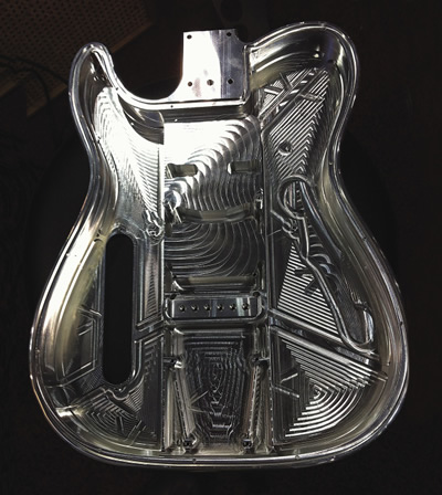
Wolfert Tool & Machine Co. Inc., St. James, Mo., says it employs the same Mastercam Dynamic Motion technology it uses to make thin-walled parts for aerospace customers as it does to manufacture single-billet aluminum Metalin guitar bodies, which are light, strong and have excellent tone quality. Images courtesy CNC Software.
Bury the Hatchet
Effective toolpaths are the lifeblood of any machine shop. The more metal removed, the more critical CAM systems are to part quality, tool life and shop profitability. What were once simple racetrack-style offset toolpaths have evolved into smart motions that dynamically adjust approach angles and feed rates to minimize stress on cutting tools while maximizing metal-removal rates.
Ben Mund, senior marketer at CNC Software Inc., Tolland, Conn., said the company’s latest release, Mastercam X8, includes a revamp of its 5-year-old Dynamic Motion technology. “Rather than offsetting the part geometry a set amount, Dynamic toolpaths are based on the material-removal rate. They essentially ignore the shape of the part in favor of consistent tool load.”
Dynamic Motion produces toolpaths that some machinists might shake their heads at, Mund said. “A traditional toolpath looks logical. It uses regular step-over amounts that, as a rule, follow the part shape. Dynamic toolpaths, on the other hand, appear chaotic. The cutter shifts to maintain constant engagement without regard to part geometry.”
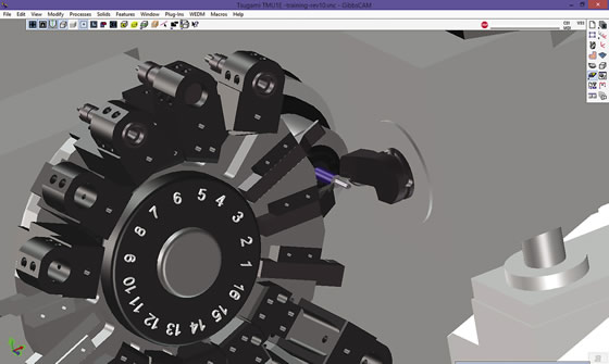
GibbsCAM toolpath simulation shows two tools cutting simultaneously on a Tsugami TMU1 Swiss-style machine. Image courtesy Gibbs and Associates.
This may seem counterintuitive, he noted, but the upside is tremendous—chip load and, therefore, heat is reduced, so more of the tool’s length can be engaged, extending tool life. And, because the tool is constantly engaged, stress on the machine tool is reduced without the lifting and repositioning common with many toolpaths.
No one would argue that burying the tool like this reduces the number of passes. Using a ½ " cutter to hog a pocket, for example, a traditional CAM system might generate three to four passes at 50 percent of the cutter width. Dynamic programming, on the other hand, might machine the pocket in a single full-depth pass, using a cut width of 5 to 10 percent and a feed rate two to three times faster. According to Mund, this approach can reduce cycle time up to 75 percent. And, because cutting forces are reduced and tool life improved, a single tool can often be used for many more operations.
Do Me a SolidAnother CAM developer with an eye toward consistent chip load is SolidCAM Inc., Newtown, Pa. Ken Merritt, senior applications engineer, said the company 's iMachining CAM module, which is integrated into SolidWorks CAD software from Dassault Systèmes SolidWorks Corp., uses “feed advance " to maintain chip thickness. “As the toolpath morphs to accommodate changing part geometries, the cutting angle changes, " he said. "By advancing or retarding the feed rate to compensate, we’re able to keep chip load within a preset tolerance band throughout the cut. This prevents harmonic shock to the tool and maintains cutting at a comfortable, predictable level.”
Merritt said iMachining’s variable step-overs and morphing spiral toolpaths move far beyond the racetrack model. “Using old-fashioned step-overs means frequent repositioning of the tool,” he said. “We avoid this with analysis of the regional geometry of the part model, optimizing the cutting regions so the tool isn’t bouncing from one side of the part to the other. This means less wear and tear on the spindle and axis motors, and a 70 percent or greater reduction in cycle time.”
SolidCAM includes wizards and various geometry experts to simplify complex programming tasks. According to Merritt, this boils code generation down to answering a handful of questions about material, machine configuration and cutting conditions.
SolidCAM and Mastercam continue to tighten the integration with SolidWorks and other third-party programs. Attendees at the SolidWorks World 2015 conference, held Feb. 8-11 in Phoenix, learned that Mastercam’s version X9, currently in public beta testing, allows users to run the integrated version of SolidWorks at no additional cost.
Wild and Crazy GuysThey’re not alone. Gibbs and Associates Inc., Moorpark, Calif., announced at IMTS 2014 that GibbsCAM would include a no-cost version of VoluMill’s ultrahigh-performance toolpath option from Celeritive Technologies for customers using Gibbs ' Production Milling software. And just this year, President Bill Gibbs upped the ante on multiaxis machining with GibbsCAM 2015, which might be thought of as the “Erector Set” of CAM systems.
“About 5 years ago we started working on Universal Kinematic Machine, a new architecture, " he said. "Our goal was to come up with a way of defining any machine with any number of axes doing any type of machining process.”
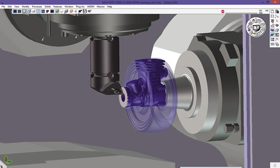
Facing an offset casting on a DMG Mori NTX 1000 as displayed on GibbsCAM’s Universal Kinetic Machine. Image courtesy Gibbs and Associates.
According to Gibbs, UKM simplifies modeling and programming of complex machines, makes post-processing faster and makes it easier and simpler to create more accurate toolpath simulations. The software uses an internal programming structure the company calls “a kinematic tree.” This allows users to define multiaxis, multispindle machine configurations where “you can move the part, move the tool, move the spindle—it doesn 't matter because all the basics are handled,” he said. “UKM accommodates these wild and crazy machines, yet toolpath creation remains a simple task.”
The Show Me StateMachining efficiency largely comes down to the effectiveness of the toolpath. Whatever the CAM system’s capabilities, the generated G code must be correct or bad things happen. The CAM programs discussed here provide modeling capabilities, but, at the same time, either partners with or offers direct interfaces to third-party toolpath verification tools. This raises a basic question: When is investment in additional CNC simulation and verification necessary?
To Gibbs, the answer is simple. CAM-based simulation is an ideal method of program prove-out, but for complex Swiss-style, multitask and 5-axis machines, investment in a G-code simulator is often warranted. “Even with customers using both types of program verification, we advise everyone to do a careful prove-out on the machine before hitting the cycle start button,” he said. “The last thing in the world you want is to crash a million-dollar machine.”
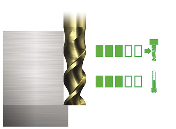
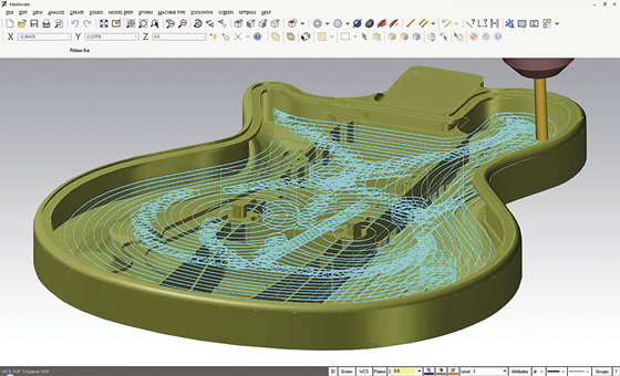
A full DOC, using a toolpath generated by Mastercam Dynamic Motion technology, delivers both even heat and load distribution. This allows deeper and faster cutting while maintaining even wear on the tool, according to CNC Software. Image courtesy CNC Software.
Silvère Proisy agreed. As general manager of SPRING Technologies Inc., Boston, Proisy spends his days spreading the good word of machine simulation. He explained the primary difference between the company’s NCSIMUL Machine and CAM-based simulation is that dedicated simulation products actually read the G code rather than relying on the output of the CAM system’s post-processor to get it right. This generates a more accurate simulation, he said, something that’s especially important with mill/turn and other complex machines.
Simulation packages do more than check for tool interference and potential crashes. According to Proisy, NCSIMUL Machine optimizes the G code, reducing cycle times up to 20 percent. “Optimization looks at several factors, including feeds and speeds, chip thickness, depth of cut and so on. Based on this, the feed rate can be automatically regulated, becoming more aggressive where possible and backing off when necessary. It’s also important to look for areas of wasted cutting motion and convert those into rapid movements.”
Like its CAD/CAM cousins, NCSIMUL Machine integrates with a broad swath of manufacturing software, including GibbsCAM and Mastercam. Direct integration to the machine control is likewise on the uptick—where better to do a “show and tell” of the CNC program than at the CNC itself?
Modeling the WorldSome shops might steer clear of in-depth program and machine simulation because of the effort involved with creating models for every tool, fixture, chuck and clamp. Add to this the need for dimensionally accurate models of each machine tool and many might be tempted to say, “Close enough, just make some chips.” Without a proper virtual environment, however, interference checking is a guessing game.
Luckily, another software “meet and greet” is taking place in the toolcrib. Proisy promotes digital tool management platforms such as Iscar’s IQ Cloud and Kenna- metal’s NOVO, together with cloud-based product data services from Machining Cloud, as logical places for shops to manage tool and fixture data. By doing so, manufacturers can eliminate the need to reinvent the tooling wheel, something that benefits CAM-based and third-party simulation aficionados alike.
Sandvik Coromant Co., Fair Lawn, N.J., is part of this growing movement. Ramaraya Bhat, business efficiency and services manager, is quick to point out that the Adveon cutting tool library system, which it helped develop, is brand neutral. “Adveon is like Amazon. It was developed with the help of CAM companies and toolmakers. Adveon adheres to the ISO 13399 standard, which Sandvik Coromant was instrumental in developing. Also, Adveon is sold by CAM companies and does not come preloaded with anyone’s tooling catalog.”
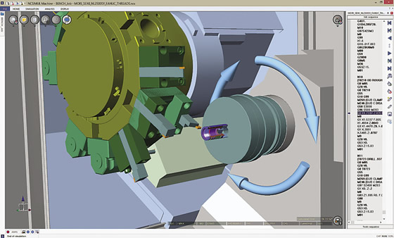
G-code simulation is more important as machine complexity grows. Here, a subspindle turning operation is simulated on a DMG Mori NL2500SY mill/turn center using NCSIMUL Machine software from SPRING Technologies. Image courtesy SPRING Technologies.
That said, Adveon works with tools from companies such as Sandvik Coromant, Kennametal, Iscar, Seco Tools, Walter and Mitsubishi Materials, and continues to pursue others willing to follow the ISO 13399 standard.
Bhat said ISO 13399, together with Sandvik Coromant’s Generic Tool Classification, harmonizes tooling nomenclature. Finally, each toolmaker will speak the same tool language—the parameter DC will mean cutting diameter, CHW signifies corner chamfer width, and DAXIN refers to axial groove inside diameter minimum, regardless of whose logo is on the tool. No more confusion for programmers, operators, toolcrib managers or procurement people.
Also, Adveon and competing systems carry electronic data about tool dimensions. This makes virtual building and qualification of tool assemblies possible, and allows shops to store digital tooling information. Further, most CAM systems and simulation software can import this information, eliminating the need to reenter data. Likewise, using the MTConnect communication protocol, CNCs and tool presetters can communicate with digital tool libraries.
The pace of change in manufacturing software can be daunting, but there 's no getting away from it. The good news is that even as it becomes more complex, CAM software developers are working on ways to make it easier to implement—a key factor as computers take over more and more of the machining process. CTE
About the Author: Kip Hanson is a contributing editor to CTE. Contact him at (520) 548-7328.
Related Glossary Terms
- backing
backing
1. Flexible portion of a bandsaw blade. 2. Support material behind the cutting edge of a tool. 3. Base material for coated abrasives.
- bandsaw blade ( band)
bandsaw blade ( band)
Endless band, normally with serrated teeth, that serves as the cutting tool for cutoff or contour band machines.
- chuck
chuck
Workholding device that affixes to a mill, lathe or drill-press spindle. It holds a tool or workpiece by one end, allowing it to be rotated. May also be fitted to the machine table to hold a workpiece. Two or more adjustable jaws actually hold the tool or part. May be actuated manually, pneumatically, hydraulically or electrically. See collet.
- computer numerical control ( CNC)
computer numerical control ( CNC)
Microprocessor-based controller dedicated to a machine tool that permits the creation or modification of parts. Programmed numerical control activates the machine’s servos and spindle drives and controls the various machining operations. See DNC, direct numerical control; NC, numerical control.
- computer-aided design ( CAD)
computer-aided design ( CAD)
Product-design functions performed with the help of computers and special software.
- computer-aided manufacturing ( CAM)
computer-aided manufacturing ( CAM)
Use of computers to control machining and manufacturing processes.
- depth of cut
depth of cut
Distance between the bottom of the cut and the uncut surface of the workpiece, measured in a direction at right angles to the machined surface of the workpiece.
- feed
feed
Rate of change of position of the tool as a whole, relative to the workpiece while cutting.
- fixture
fixture
Device, often made in-house, that holds a specific workpiece. See jig; modular fixturing.
- gang cutting ( milling)
gang cutting ( milling)
Machining with several cutters mounted on a single arbor, generally for simultaneous cutting.
- milling
milling
Machining operation in which metal or other material is removed by applying power to a rotating cutter. In vertical milling, the cutting tool is mounted vertically on the spindle. In horizontal milling, the cutting tool is mounted horizontally, either directly on the spindle or on an arbor. Horizontal milling is further broken down into conventional milling, where the cutter rotates opposite the direction of feed, or “up” into the workpiece; and climb milling, where the cutter rotates in the direction of feed, or “down” into the workpiece. Milling operations include plane or surface milling, endmilling, facemilling, angle milling, form milling and profiling.
- step-over
step-over
Distance between the passes of the toolpath; the path spacing. The distance the tool will move horizontally when making the next pass. Too great of a step-over will cause difficulty machining because there will be too much pressure on the tool as it is trying to cut with too much of its surface area.
- tolerance
tolerance
Minimum and maximum amount a workpiece dimension is allowed to vary from a set standard and still be acceptable.
- toolpath( cutter path)
toolpath( cutter path)
2-D or 3-D path generated by program code or a CAM system and followed by tool when machining a part.
- turning
turning
Workpiece is held in a chuck, mounted on a face plate or secured between centers and rotated while a cutting tool, normally a single-point tool, is fed into it along its periphery or across its end or face. Takes the form of straight turning (cutting along the periphery of the workpiece); taper turning (creating a taper); step turning (turning different-size diameters on the same work); chamfering (beveling an edge or shoulder); facing (cutting on an end); turning threads (usually external but can be internal); roughing (high-volume metal removal); and finishing (final light cuts). Performed on lathes, turning centers, chucking machines, automatic screw machines and similar machines.
Author

Kip Hanson is a contributing editor for Cutting Tool Engineering magazine. Contact him by phone at (520) 548-7328 or via e-mail at [email protected].