Lean manufacturing is much more than a buzzword. It is a potent concept that has aided many manufacturers, large and small.
Lean manufacturing involves using processes that have been simplified via advanced technology to produce more with less manpower while continuously improving quality and reducing lead times. The paradox of lean is that when everything has been stripped to the bare essentials to boost productivity, no one has much time left to capture, assimilate and implement the knowledge needed to adopt new labor-saving technologies.
Derek Goodwin, president of manufacturing consultancy Goodwin Manufacturing Group, Morgan Hill, Calif., is out to change this conundrum. The group offers packages of CAM-centric services that bridge the gap between the acquisition of advanced manufacturing systems and fully using their capabilities to boost productivity and reduce costs.
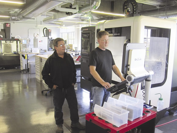
Derek Goodwin (left), president of Goodwin Manufacturing Group, works with Lime Lab Inc. Prototyping Manager Chris Iverson to get a DMG Mori DMU50 5-axis vertical machining center operating near its full potential within weeks of installation.
Goodwin’s team starts by evaluating the business objectives that drive the acquisition of a new technology and how this technology can be integrated with the company’s existing CAM processes.
“CAM is central to managing everything that happens on the shop floor,” he said. “It is the place where we can review our process from beginning to end and get everything right before we start making chips.”
When serving customers, the Goodwin Manufacturing Group is CAM-vendor neutral, striving to take advantage of the strengths of whatever CAM software a customer has. Goodwin and his staff, however, are long-time users of Mastercam from CNC Software Inc., Tolland, Conn.
Essential Steps
Once the business goals have been formulated, Goodwin’s team implements a four-step process:
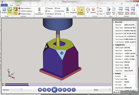
With Mastercam for SolidWorks, prototypers can do all of their work, including writing and simulating CNC toolpaths, within the SolidWorks programming environment.
With this process, Goodwin said his company can implement technology acquisitions and process improvements in weeks that would take a customer’s internal teams months to complete. One element that moves the process along quickly is knowing the CAM software’s strengths and how they might be applied to bridge gaps that prevent advanced manufacturing systems from operating efficiently.
Manufacturers often fail to adequately address cycle-time reduction because of time constraints, according to Goodwin. This means they are missing out on the interrelated knowledge regarding workpiece materials, workholders, controls, thermal dynamics and cutting tools, which continues to advance. This knowledge can be aggregated to achieve greater material-removal rates than could be conceived of even 5 years ago.
A typical project to reduce cycle time involves determining why a particular part or family of parts consumes the machining time it does, Goodwin explained. Once his team has uncovered the root causes, they implement a new process and provide training, documentation and often a video to show others how to replicate what they did.
In one project involving manufacturing a family of parts on a 5-axis machine, Goodwin’s team reduced the machining cycle from almost 4 hours to 20 minutes. He noted the bulk of this reduction was achieved using Mastercam’s Dynamic Motion technology, which automatically adjusts feeds, speeds and cutting tool entries based on the real-time condition of material ahead of the tool. This avoids burying the tool, allowing a manufacturer to confidently run at the highest feasible mrr and reduce tool wear.
In addition, Goodwin attributed about 20 percent of the cycle-time reduction to developing a custom post-processor to resolve short-distance servo acceleration and deceleration issues that prevented the machine from achieving its inherent high-speed machining capabilities.
Bullet Proofing a Post
A number of issues must be resolved before a 5-axis machine can achieve its full potential. Goodwin explained that there is a widespread misconception that an end user just calls a post developer and orders a post for a particular machine. This is only the beginning of the process. Within the post, dozens of places exist that require decisions about what the post should instruct the machine to do. Some of these are technically complex, while others are just preferences regarding myriad elements, from retract distances to coolant timing.
Post developers typically resolve these issues by sending the client a long questionnaire. Determining these little details can be time-consuming and is based on understanding what code the CAM system will output and how a specific control will respond.
Customers who provide answers off the top of their heads will likely be disappointed in the first draft of the post, and its development will drag on while the equipment is unutilized or underutilized. For post-processor development, the Goodwin Manufacturing Group frequently takes on the role of customer surrogate, giving post developers all the needed details.
Even when most of these issues have been meticulously addressed, there can be surprises. As a result, new 5-axis posts must be rigorously proven before they become part of a manufacturing process. The most demanding test involves making a complex part that requires simultaneous 5-axis machining.
For one contract manufacturer, the group implemented a 5-axis process on the rotary table of a twin-table horizontal mill. “It was a brand new machine and they did enough 5-axis work to know that the process must be thoroughly proven before it could be offered to customers without the risk of violating their lead-time expectations,” Goodwin said. “We decided the best test for this post would be manufacturing a blisk. Programming a blisk can be very complicated and this company had not yet written the program. We bridged this gap by installing Mastercam’s Blade Expert software, which creates complete blisk programs simply by having the programmer enter data in a pop-up table in the software.”
The project was completed in a few weeks. The manufacturer not only wound up with a proven 5-axis machining system and post-processor, but also a process for generating programs for blisks and blades.
Co-location and Collaboration
In 2013, Goodwin Manufacturing Group consulted with a design and prototyping company to select and integrate software and equipment for a new laboratory equipped with advanced 3-D printers, multiaxis CNC machine tools, digital die-cutting equipment and networked CAD and CAM software. Design engineers and prototype manufacturing staff are co-located at the facility.
“We are using Mastercam for SolidWorks to bridge the gap that usually prevents bidirectional communication between engineers who primarily use CAD and prototype technicians who live in the world of CAM,” Goodwin said. “Within this fully integrated CAD/CAM environment, cross-discipline interaction and collaboration is not only encouraged, it is inevitable. Engineers routinely tap into the inherent manufacturing experience of the shop guys when they are designing products. As a result, innovative products get to market sooner, as prototypers have many opportunities to infuse their design-for-manufacturing insights early and often throughout the design process.”
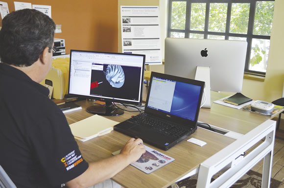
Derek Goodwin uses Mastercam Blade Expert software to develop a test program to prove out the post-processor for a customer’s new 5-axis machining center.
Many companies miss the boat because they do not take the time to discover technologies that can make manufacturing far more efficient, according to Goodwin. For example, simply learning to use the tool motion strategies found in CAM programs can reduce cycle times by 25 percent or more.
The idea that manufacturers are so busy they cannot find time to understand, adopt and assimilate transformative technology is an oversimplification. Goodwin added that some shops do find the time and do a good job of on-boarding technologies that make them more competitive—but at a cost. Typically, this process diverts their most talented people from other important duties or dilutes their attention among many projects.
By having a CAM-centric manufacturing consultancy develop a project and leave an infrastructure in place for repeated use, a manufacturer can implement a new machining technology significantly quicker. “Our clients generally recover our costs well before their internal teams would have completed the project,” Goodwin said.
For more information about Goodwin Manufacturing Group, call (408) 612-8910 or visit www.goodwinmanufacturing.com. CTE
About the Author: Doug Nemeth is the corporate sales engineering manager for CNC Software Inc., Tolland, Conn. For more information about the company’s Mastercam CAD/CAM software, call (800) 228-2877 or visit www.mastercam.com.
Related Glossary Terms
- 3-D
3-D
Way of displaying real-world objects in a natural way by showing depth, height and width. This system uses the X, Y and Z axes.
- computer numerical control ( CNC)
computer numerical control ( CNC)
Microprocessor-based controller dedicated to a machine tool that permits the creation or modification of parts. Programmed numerical control activates the machine’s servos and spindle drives and controls the various machining operations. See DNC, direct numerical control; NC, numerical control.
- computer-aided design ( CAD)
computer-aided design ( CAD)
Product-design functions performed with the help of computers and special software.
- computer-aided manufacturing ( CAM)
computer-aided manufacturing ( CAM)
Use of computers to control machining and manufacturing processes.
- coolant
coolant
Fluid that reduces temperature buildup at the tool/workpiece interface during machining. Normally takes the form of a liquid such as soluble or chemical mixtures (semisynthetic, synthetic) but can be pressurized air or other gas. Because of water’s ability to absorb great quantities of heat, it is widely used as a coolant and vehicle for various cutting compounds, with the water-to-compound ratio varying with the machining task. See cutting fluid; semisynthetic cutting fluid; soluble-oil cutting fluid; synthetic cutting fluid.
- family of parts
family of parts
Parts grouped by shape and size for efficient manufacturing.
- lean manufacturing
lean manufacturing
Companywide culture of continuous improvement, waste reduction and minimal inventory as practiced by individuals in every aspect of the business.
- machining center
machining center
CNC machine tool capable of drilling, reaming, tapping, milling and boring. Normally comes with an automatic toolchanger. See automatic toolchanger.
- milling machine ( mill)
milling machine ( mill)
Runs endmills and arbor-mounted milling cutters. Features include a head with a spindle that drives the cutters; a column, knee and table that provide motion in the three Cartesian axes; and a base that supports the components and houses the cutting-fluid pump and reservoir. The work is mounted on the table and fed into the rotating cutter or endmill to accomplish the milling steps; vertical milling machines also feed endmills into the work by means of a spindle-mounted quill. Models range from small manual machines to big bed-type and duplex mills. All take one of three basic forms: vertical, horizontal or convertible horizontal/vertical. Vertical machines may be knee-type (the table is mounted on a knee that can be elevated) or bed-type (the table is securely supported and only moves horizontally). In general, horizontal machines are bigger and more powerful, while vertical machines are lighter but more versatile and easier to set up and operate.
- tap
tap
Cylindrical tool that cuts internal threads and has flutes to remove chips and carry tapping fluid to the point of cut. Normally used on a drill press or tapping machine but also may be operated manually. See tapping.