Having the proper CAD/CAM system is critical when machining parts. Presented here are the answers to 10 key questions about how to determine the right CAD/CAM system for your operation.
1. What should I look for in a CAD/CAM system when considering lights-out machining?
The system must reliably output NC data on nonproduction parts, such as tooling and prototypes. Many software developers make that claim, but care should be taken in evaluating if the system can provide reliable toolpaths, machining simulation, automatic tool changes, laser calls to validate tool wear and automatic selection of sister, or backup, tools.
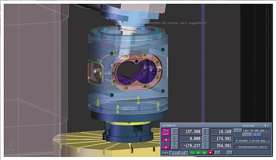
A CAD/CAM system should provide virtual machining, or machine simulation, for planning, testing and optimizing toolpaths. All images courtesy Tebis America.
2. Can all CAD/CAM systems handle large data sets?
“Large” means physical part size or the number of bytes the file occupies on a computer. Not all CAD/CAM systems effectively handle these types of files. The system should be able to handle them in both the CAD and CAM sides. It makes no sense to have separate CAD and CAM systems because your files are too big.
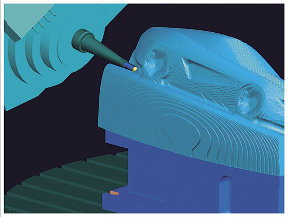
Implement 3+2 roughing with 3D stock model for machining steep and undercut areas.
3. Do I really need powerful machining strategies in a CAM system?
Many systems use the same naming conventions but their output results vary. Having real “high-end” strategies enables optimal machining times, long tool life and fine surface finishes with less user effort.
4. How important is it for the CAD/CAM team to fully explore all software functions?
While majority of users do not fully explore all functions available in their systems, training users on the latest functions in new releases is an excellent investment. Many software developers provide technical information and tips and tricks through webinars, newsletters and training videos. Motivate your CAD/CAM team to make use of these tools.
5. Should I consolidate the different CAD/CAM systems in my shop?
Many shops are consolidating their CAD/CAM systems and retiring legacy systems. If one system can provide exceptional CAD, CAM and QC functions, it makes sense to consolidate various systems, especially when it eliminates dealing with multiple CAD/CAM vendors. You get the added benefits of not having to deal with multiple systems and achieving data transparency from the same vendor. This transparency requires avoiding data inconsistency when moving data between a CAD and CAM system.
6. Should I worry about how quickly technical support responds to an issue when considering a CAD/CAM system?
Imagine you are programming a complex part while struggling with software errors, and your delivery time is short so you don’t have time to experiment with different machining strategies. Technical support that quickly responds to serious problems like this one is a must.
7. What features should the CAM system have to NC program complex 3D shapes?
For these shapes, the CAM software must have the following:
8. How do I standardize NC pro-gramming processes to achieve consistency when milling?
The CAM software should handle data coming from different CAD systems. Depending on customer requirements, companies follow their internal standards during the design process by applying different colors to entities, layer names, group names and attributes. CAM software should be able to analyze these different data sets and apply predefined machining templates to automate the CAM-generation process. This process not only automates CAM programming, but also standardizes processes throughout the shop.
9. Is CAM programming on the shop floor a better solution than programming in a CAM room?
Many part manufacturers have found advantages to programming on the shop floor. For example, CAM programs can be generated on the fly without waiting for a program from the CAM room, so delays in programming and job deliveries don’t occur. In addition, the machine operator has more knowledge about how to best mill the part with the correct tools and machining parameters and, therefore, will have full control when programming toolpaths on the shop floor. This improves productivity by avoiding process arguments between CAM room programmers and shop floor users.
10. Should the system I’m looking to buy be market-driven or development-driven?
Many CAD/CAM features are driven by software development teams and not by the end users or market demand. As a result, many systems don’t take user needs into account during the development process. Target developers that focus on customer needs and product features that were implemented over several years when selecting new CAD/CAM software. CTE
Related Glossary Terms
- computer-aided design ( CAD)
computer-aided design ( CAD)
Product-design functions performed with the help of computers and special software.
- computer-aided manufacturing ( CAM)
computer-aided manufacturing ( CAM)
Use of computers to control machining and manufacturing processes.
- milling machine ( mill)
milling machine ( mill)
Runs endmills and arbor-mounted milling cutters. Features include a head with a spindle that drives the cutters; a column, knee and table that provide motion in the three Cartesian axes; and a base that supports the components and houses the cutting-fluid pump and reservoir. The work is mounted on the table and fed into the rotating cutter or endmill to accomplish the milling steps; vertical milling machines also feed endmills into the work by means of a spindle-mounted quill. Models range from small manual machines to big bed-type and duplex mills. All take one of three basic forms: vertical, horizontal or convertible horizontal/vertical. Vertical machines may be knee-type (the table is mounted on a knee that can be elevated) or bed-type (the table is securely supported and only moves horizontally). In general, horizontal machines are bigger and more powerful, while vertical machines are lighter but more versatile and easier to set up and operate.
- numerical control ( NC)
numerical control ( NC)
Any controlled equipment that allows an operator to program its movement by entering a series of coded numbers and symbols. See CNC, computer numerical control; DNC, direct numerical control.
- undercut
undercut
In numerical-control applications, a cut shorter than the programmed cut resulting after a command change in direction. Also a condition in generated gear teeth when any part of the fillet curve lies inside of a line drawn tangent to the working profile at its point of juncture with the fillet. Undercut may be deliberately introduced to facilitate finishing operations, as in preshaving.