Production of precise, tough oil-field components demands the use of sophisticated multitask machines.
Contrary to its image as dirty and primitive, oil drilling today is a cleaner, highly technical and productive process. Deep-hole undersea operations, especially, employ tight-tolerance components made of exotic alloys. To achieve those tolerances and maximize throughput, machine shops that manufacture for the oil-patch industry are increasingly using multitask machine tools that help minimize setups and part handling while boosting metalworking productivity.
The ongoing tumult in oil markets and prices stirs uncertainty for shops that serve the oil-patch industry. (See sidebar on page 35.) There is at least one certainty about the industry, though. “The world still runs on oil and gas,” said David Williams, chief executive of offshore drilling contractor Noble Corp., in the Houston Chronicle. “The meltdown in the financial sector and the loss of confidence in the equity markets have not changed this fundamental fact.”
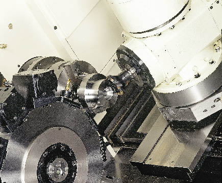
Courtesy of Methods Machine Tools
The B-axis spindle and driven tool stations on the lathe turret expand the capabilities of this Nakamura-Tome STW-40 mill/turn center beyond turning and on-axis drilling operations.
The newspaper also quoted Eric Smith, associate director of the Tulane Energy Institute in New Orleans, who said, “We look around at where our oil is coming from, and the growth is in deep-water production.”
Deep-water drilling, however, involves massive physical challenges. An example is the Jack 2 well in the Gulf of Mexico, a joint venture of Chevron, Devon Energy and Statoil Hydro. The drill string (consisting of drill pipe, drill collars, tools and the drill bit) descends more than 5 miles, passing through 7,000 ' of seawater and more than 20,000 ' of seafloor to reach oil.
Deep Dependability
Deep-water drilling also involves components with the high precision and reliability usually associated with aerospace components. Rich Parenteau, director of applications development at Methods Machine Tools Inc., Sudbury, Mass., used as an example a drill head machined from a corrosion-resistant stainless alloy. “From the tolerance level, less than 0.001 " all the way around, you would think these things are going into aircraft,” he said. “They cannot afford to have a failure when this thing is down there 2 or 3 miles.”
As the drills go deeper, performance requirements become more rigorous and manufacturing processes for the drill heads change. Formerly assembled from individual parts, drill heads today are generally machined from a single piece of stock. “These drill heads are running 30,000 psi of flushing fluid to maintain the clearance in the hole,” Parenteau said. “You cannot rely on a multipart configuration—it’s not strong enough—and the failure potential is too great. For strength and reliability, the drillers want one-piece construction.”
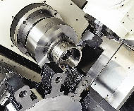
Courtesy of Methods Machine Tools
Turning tools in both the lathe turret and B-axis spindle of this Nakamura-Tome STW-40 mill/turn center permit both ID and OD machining.
Parenteau explained that a typical drill head, ranging in diameter from 8 " to 10 ", is machined from a durable, corrosion-resistant material, such as stainless steel or Inconel. On the head’s back end is a special tapered thread that endures drilling forces and resists the pressure of the flushing fluid. To maintain geometric tolerance requirements, including true position and perpendicularity to centerline, many shops are adopting multitask machine technology to produce the head in one chucking. A single setup for turning, milling and drilling avoids the possibility of errors and tolerance stack-up that can occur when moving a workpiece from machine to machine.
Parenteau said one Texas shop had a number of 5-axis milling machines, but felt the need to adopt mill/turn technology to achieve consistent geometric tolerances, specifically in the case of a proprietary drill head’s tapered thread. “The tolerance was so critical he felt it was best to do it as a one-shot operation,” Parenteau said.
Consequently, Methods Machine Tools provided a Nakamura-Tome STW-40. The mill/turn center includes twin 40-hp turning spindles and twin turning-tool turrets that each have a 12-tool capacity. A 20-hp, B-axis upper spindle is served by a 40-tool automatic toolchanger (ATC). Also, each of the lower turrets’ 12 stations have a 10-hp driven tool capability for milling and drilling.
The B-axis capability facilitates the production of the usually proprietary tapered threads. Although some shops cut those threads with a single-point turning tool, “the geometry of that threading tool is very particular to setup because of the tapered cone that the thread is turned on,” Parenteau said. The B-axis’ ability to circular interpolate on a compound angle permits the use of a custom key cutter to facilitate setup and produce the thread with maximum consistency.
Minimizing Moves
Dana Scott, general manager of the southwest U.S. sales region of Mazak Corp., Florence, Ky., said the production of complex oil-field parts traditionally required multiple operations on different machines. Typically, the parts waited between operations for a machine tool to become available, extending total production time. “It dawned on the oil service OEMs that they were hurting their cash flow and were hurting their customers by making them wait 3 weeks to fill an order,” Scott said. He added that by making a part in one chucking on a machine, a shop can complete and ship a part in hours instead of weeks.

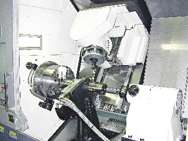
Courtesy of Hughes Christensen
Efficient machining of the GaugePro XPR expandable reamer, a concentric-hole enlargement device from Hughes Christensen, is facilitated by the deep-hole boring capabilities of the Mazak e650 H multitasking lathe.
In addition to minimizing part handling and work in process, most multitask machines offer tool-change capacity that reduces part-changeover time. “The tools you need are already on the machine,” Scott said. “Your part program is downloaded, so all you have to do when you change from one part to a different one is change the top jaws on your workholding. Your setups are minimized.”
According to Scott, a Mazak multitask machine with tool-change capacity that is popular in the oil-patch industry is the Integrex e650 H. The machine’s 60-hp main spindle features a full C-axis and a standard spindle bore of 6.69 ", with an optional 10.24 " spindle bore. “Sometimes larger-diameter spindle bores are needed, not just to swallow a part, but to accommodate the weight of some of the big parts,” Scott said. “The larger-diameter spindle bearing will support more weight.” With a 24 "-dia. chuck, the machine’s maximum turning diameter is 36 ". The machine’s 50-hp B-axis spindle provides a 240° range of travel, positions in 0.0001° increments and can perform full 5-axis contouring.
One of the Mazak e650 H’s key features is an automatic boring bar stocker that can handle tools up to 39 " long in standard configuration, with an optional 60 " capacity for even deeper holes. According to Doug Whitsitt, purchasing manager at the Hughes Christensen division of Baker Hughes Inc., Houston, this deep-hole boring capability is an important contributor to productive machining of the company’s GaugePro XPR expandable reamer. The reamer is a concentric-hole enlargement device with cutter blades that extend from the tool body. In use, the reamer is mounted in the drill string behind a drill bit and eliminates the need to pull (“trip out”) the drill string and make a second pass with a larger-diameter drill. “On extremely deep wells in the Gulf of Mexico, tripping out to change the drill bit is a long, tedious and expensive process. If you have a million-dollar day rate and it takes you all day to trip out and back in, you are not making any hole, but you are still paying,” Whitsitt said.
The reamers are produced in three sizes covering maximum reamed hole diameters from 12¼ " to 17½ ". The reamer body is machined from a solid bar of forged 4330 steel and doesn’t have any welded components. “A weld could come apart. One-piece construction is not going to come apart,” Whitsitt said.
On the e650 multitask machine, Hughes Christensen OD turns and bores the tool body, mills pockets for the extendable blades and machines wear pads to protect the tool body. The tool’s ID has a complex profile to accommodate the operating mechanism for the blades. “The hard part about that [ID] is it’s 37 " deep,” Whitsitt said. To profile the hole, the shop employs a 72 "-long, custom steel-and-carbide boring bar from Kennametal Inc. (The machine has a 60 " bar option, and the holder absorbs the bar’s extra length.) “The bar is tunable, so you can take the vibration out,” Whitsitt said.
The longest reamer the shop bores on the machine is 97 " long. “The machine will take a longer part, but you have to have enough at the end of the reamer to allow that bar to go in. We have maybe 1½ " or 2 " from the end when we put that long boring bar in there,” Whitsitt said. The machine provides 160 " between centers, and “we are maxing that out,” he added.
Whitsitt said the reamer can achieve a tolerance of 0.005 "/-0.000 ". “When you go 40 " deep, that’s a close tolerance, and we produce a 63 µin. Ra finish to boot.”
Whitsitt said the reamers can be manufactured via a lathe and a milling machine and the total machining time may be comparable to that of a mill/turn center—if the machines were sitting idle. But machines do not sit idle in a well-managed shop, so they wouldn’t be immediately available for machining the reamers. “You would end up queuing the parts, and it could change what we are doing in 40 hours on the Mazak to a couple weeks, depending on how many machine tools you have,” Whitsitt said.
Two Tools Together
Mike Spink, regional sales manager for the engineering technologies division of machine tool builder Phillips Corp., Hanover, Md., discussed a machine tool that increased a Louisiana machine shop’s productivity through the machine’s simultaneous operation of two turning tools.
The shop makes blowout preventers, a key component of every oil well. According to Spink, blowout preventers for drilling on land are usually made from standard forged steels, but they’re made of corrosion-resistant, difficult-to- machine exotic alloys when used for drilling in high-pressure, corrosive subsea environments.
Spink outlined the details of an Olympia machine tool engineered by Phillips Engineering Technologies to handle 50 "-dia. blowout preventers. The parts “looked like jet nozzles, and they were running them out of nickel-chrome material. This stuff was just really bad, hard and ugly. I don’t know any other way to say it. You start looking at parts that are 38 to 44 HRC in a soft state, and that’s bad.” The part had to be bored, turned and drilled in 10 places for bolt holes. Four of the holes were then bored to diameters of about 8½ ".
In bidding on the job, Phillips competed against a 5-axis machining center with an A-axis head and a turntable. Cycle time to produce the part on the machining center was about 8 hours.
Phillips proposed an 80-hp Olympia vertical turning lathe with a 40 "-dia. table, 60 " swing capacity, and 30 " height under the tool block. The machine featured twin 9.8 "-square rams (each with a 30 " Z-axis travel), 40-hp live spindle capability and a rotary 24-position toolchanger. The twin rams permitted simultaneous operation of two turning tools, which balanced the cutting forces. “When taking off 200 to 300 pounds of really hard material, pulling those cuts on the turning center was a huge, critical factor,” Spink said. The twin turning tools doubled turning productivity. Drilling and boring times were cut in half, too. Applying the two rams’ live spindles simultaneously, “we had symmetrical holes so we were boring holes number one and four at the same time,” Spink said. On the Olympia machine, the part’s cycle time was about 3½ hours.
However, Spink said the Olympia machine was application-specific, that the competing machining center would be effective on aluminum or free-machining steel, but not on difficult-to-machine materials.
Multiple Choices
Tim Thiessen, a senior sales manager with Okuma America Corp., Charlotte, N.C., said Okuma’s Mac Turn 550 mill/turn center can machine large, complex parts in one chucking. The largest of the Mac Turn machine tools, the 550, can handle workpieces up to 28 " in diameter and 120 " long. Its 3,500-rpm primary and secondary turning spindles offer 40 hp and 30 hp, respectively. Its B-axis features a 5,000-rpm, 30-hp spindle in an upper turret position. A 50-tool ATC is standard.
Courtesy of Extel Precision Machining
An Okuma Multus B400 lathe features multitasking capabilities that enable Extel Precision Machining to turn, mill and drill parts like this titanium down-hole electronics chassis in a single setup.
Courtesy of Extel Precision Machining
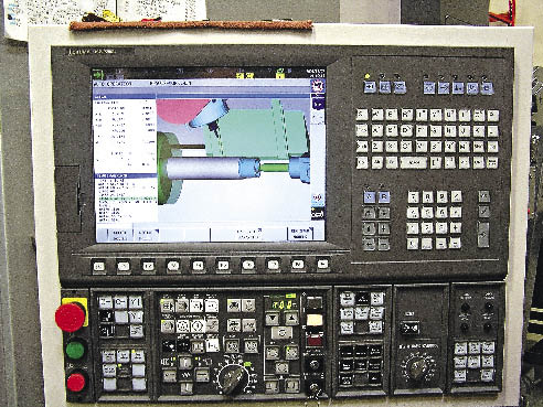
The control panel screen of an Okuma Multus B400 lathe at Extel Precision Machining displays a simulation of multitask machining operations for the down-hole electronics chassis.
Andy Hodgkinson, vice president for corporate development for Extel Precision Machining, Inc., Houston—a growing shop servicing the energy industry—said Extel is applying Okuma multitask machines to eliminate multiple setups on multiple machines. On traditional single-purpose machine tools, some of the shop’s more complex parts would require multiple lathe setups, at least one vertical setup for radial milling and multiple horizontal setups for gundrilling and end work. Each setup would require indicating the tight-tolerance parts to within 0.001 ". “The fact that we can transfer parts on the subspindle machine and hold 0.002 " on linear dimensions, and perform multiple operations without manually touching the part is an incredible time saver for us,” Hodgkinson said. He added that “The rigidity and repeatability of the machines is key to being able to perform this kind of work in exotic alloys, which comprise 90 percent of our tight-tolerance work.”
Thiessen said multitask machines can boost productivity and throughput, but they require increased operator skill and responsibility compared to less complex machines. “One of the challenges with a machine like this is to find an operator who can learn the control of all of these axes. Considering that these parts are made of high-value material and require extensive process time, it is critical that parts not be lost to operator, programming or machine error.”
However, Thiessen said multitasking on a single machine may not always be the answer. “There are a couple schools of thought for multitask parts. One school says to combine as much as possible on a single machine. Another is to separate the processes on multiple machines. Much of this depends on the volume of parts you need to run, the challenges in workholding and the geometries and accuracies that must be maintained on the part from feature to feature or volumetrically.”
Oil-patch partmakers must deal with the continual pressure of competing for demanding customers, while the products they make must handle pressure generated by miles of seawater and earth. Multitask machine tools help oil-patch shops maximize the flow of parts through their shops while simultaneously maintaining the tight tolerances and unwavering reliability required to operate successfully in the hostile environment far below. CTE
About the Author: Bill Kennedy, based in Latrobe, Pa., is contributing editor for Cutting Tool Engineering. He has an extensive background as a technical writer. Contact him at (724) 537-6182 or by e-mail at [email protected].
Oil turmoil
It’s an unsettling time to be a shop that makes parts for the oil-field industry, not to mention being a company that sells machine tools to those shops.
However, despite falling oil prices (as of this writing in November), the oil-patch industry is booming, and shops are scrambling to buy machine tools to meet production schedules. “The sentiment in the oil business right now is that they’ve seen such radical spikes and drops that they are scared,” said Mike Spink, regional sales manager, Phillips Corp. “They look at things and say ‘I have to have a machine right now. I don’t care if it’s a better machine or a lesser machine. Hey, I need a spindle.’” Buying any available machine may be a mistake long-term, though. Spink cited different machine tool builders’ 60 " table VTLs. “They look pretty much the same,” he said. “When you start looking at the ballscrew sizes, bearing diameter sizes, the weights of the machines, the capacity of the machines, the torque generated by the machines, all these little things make a big difference in the long run.”
“We try to look for what is going to be most beneficial for the long term, and buy that [machine tool],” said Doug Whitsitt, purchasing manager for the Hughes Christensen division. Also, the division assembles a multifunctional team for its machine tool purchases. For the Mazak e650 machines, the team consisted of Whitsitt (then a manufacturing engineering manager), a maintenance man, two operators, the designer of the tools the machines would make, a programmer and a health/safety/environmental representative. “We looked very closely at the capabilities of the machines. We wanted everybody’s buy-in,” Whitsitt said.
Ron Gauthier, sales manager for machine tool builder Amera Seiki Inc., Cedar Rapids, Iowa, said there is a trend in manufacturing to machine parts in one chucking whenever possible, especially where large parts are concerned. And the opportunities to machine large parts may be growing. “More big parts are staying in this country,” Gauthier said. He added that he was in the process of quoting to a U.S. manufacturer a machine with a bed length of 275 " for machining hydraulic cylinders up to 24 " in diameter.
“A few years back, everything was going to China and India,” Gauthier said. “However, you had a big part machined in China, you saved a bundle, then you brought it back here, sent it to inspection and found out it had to be reworked. So now any money you saved is lost; time that you saved is lost; plus, relative to 4 years ago, the cost of transportation has become a killer for a big part.” Consequently, Gauthier said manufacturers are now asking, “What is the price of quality? What is the price of having to have it reworked once it gets here?”
— B. Kennedy
Contributors
Amera Seiki Inc.
(319) 730-0310
www.amera-seiki.com
Extel Precision Machining Inc.
(281) 569-3700
www.epmachining.net
Hughes Christensen
(281) 363-6000
www.bakerhughesdirect.com
Mazak Corp.
(859) 342-1700
www.mazakusa.com
Methods Machine Tools Inc.
(877) MMT-4CNC
www.methodsmachine.com
Okuma America Corp.
(704) 588-7000
www.okuma.com
Phillips Corp.
(800) 878-4242
www.phillipscorp.com
Related Glossary Terms
- alloys
alloys
Substances having metallic properties and being composed of two or more chemical elements of which at least one is a metal.
- automatic toolchanger
automatic toolchanger
Mechanism typically included in a machining center that, on the appropriate command, removes one cutting tool from the spindle nose and replaces it with another. The changer restores the used tool to the magazine and selects and withdraws the next desired tool from the storage magazine. The changer is controlled by a set of prerecorded/predetermined instructions associated with the part(s) to be produced.
- boring
boring
Enlarging a hole that already has been drilled or cored. Generally, it is an operation of truing the previously drilled hole with a single-point, lathe-type tool. Boring is essentially internal turning, in that usually a single-point cutting tool forms the internal shape. Some tools are available with two cutting edges to balance cutting forces.
- boring bar
boring bar
Essentially a cantilever beam that holds one or more cutting tools in position during a boring operation. Can be held stationary and moved axially while the workpiece revolves around it, or revolved and moved axially while the workpiece is held stationary, or a combination of these actions. Installed on milling, drilling and boring machines, as well as lathes and machining centers.
- centers
centers
Cone-shaped pins that support a workpiece by one or two ends during machining. The centers fit into holes drilled in the workpiece ends. Centers that turn with the workpiece are called “live” centers; those that do not are called “dead” centers.
- chuck
chuck
Workholding device that affixes to a mill, lathe or drill-press spindle. It holds a tool or workpiece by one end, allowing it to be rotated. May also be fitted to the machine table to hold a workpiece. Two or more adjustable jaws actually hold the tool or part. May be actuated manually, pneumatically, hydraulically or electrically. See collet.
- clearance
clearance
Space provided behind a tool’s land or relief to prevent rubbing and subsequent premature deterioration of the tool. See land; relief.
- gang cutting ( milling)
gang cutting ( milling)
Machining with several cutters mounted on a single arbor, generally for simultaneous cutting.
- gundrilling
gundrilling
Drilling process using a self-guiding tool to produce deep, precise holes. High-pressure coolant is fed to the cutting area, usually through the gundrill’s shank.
- inner diameter ( ID)
inner diameter ( ID)
Dimension that defines the inside diameter of a cavity or hole. See OD, outer diameter.
- land
land
Part of the tool body that remains after the flutes are cut.
- lathe
lathe
Turning machine capable of sawing, milling, grinding, gear-cutting, drilling, reaming, boring, threading, facing, chamfering, grooving, knurling, spinning, parting, necking, taper-cutting, and cam- and eccentric-cutting, as well as step- and straight-turning. Comes in a variety of forms, ranging from manual to semiautomatic to fully automatic, with major types being engine lathes, turning and contouring lathes, turret lathes and numerical-control lathes. The engine lathe consists of a headstock and spindle, tailstock, bed, carriage (complete with apron) and cross slides. Features include gear- (speed) and feed-selector levers, toolpost, compound rest, lead screw and reversing lead screw, threading dial and rapid-traverse lever. Special lathe types include through-the-spindle, camshaft and crankshaft, brake drum and rotor, spinning and gun-barrel machines. Toolroom and bench lathes are used for precision work; the former for tool-and-die work and similar tasks, the latter for small workpieces (instruments, watches), normally without a power feed. Models are typically designated according to their “swing,” or the largest-diameter workpiece that can be rotated; bed length, or the distance between centers; and horsepower generated. See turning machine.
- machining center
machining center
CNC machine tool capable of drilling, reaming, tapping, milling and boring. Normally comes with an automatic toolchanger. See automatic toolchanger.
- metalworking
metalworking
Any manufacturing process in which metal is processed or machined such that the workpiece is given a new shape. Broadly defined, the term includes processes such as design and layout, heat-treating, material handling and inspection.
- milling
milling
Machining operation in which metal or other material is removed by applying power to a rotating cutter. In vertical milling, the cutting tool is mounted vertically on the spindle. In horizontal milling, the cutting tool is mounted horizontally, either directly on the spindle or on an arbor. Horizontal milling is further broken down into conventional milling, where the cutter rotates opposite the direction of feed, or “up” into the workpiece; and climb milling, where the cutter rotates in the direction of feed, or “down” into the workpiece. Milling operations include plane or surface milling, endmilling, facemilling, angle milling, form milling and profiling.
- milling machine ( mill)
milling machine ( mill)
Runs endmills and arbor-mounted milling cutters. Features include a head with a spindle that drives the cutters; a column, knee and table that provide motion in the three Cartesian axes; and a base that supports the components and houses the cutting-fluid pump and reservoir. The work is mounted on the table and fed into the rotating cutter or endmill to accomplish the milling steps; vertical milling machines also feed endmills into the work by means of a spindle-mounted quill. Models range from small manual machines to big bed-type and duplex mills. All take one of three basic forms: vertical, horizontal or convertible horizontal/vertical. Vertical machines may be knee-type (the table is mounted on a knee that can be elevated) or bed-type (the table is securely supported and only moves horizontally). In general, horizontal machines are bigger and more powerful, while vertical machines are lighter but more versatile and easier to set up and operate.
- milling machine ( mill)2
milling machine ( mill)
Runs endmills and arbor-mounted milling cutters. Features include a head with a spindle that drives the cutters; a column, knee and table that provide motion in the three Cartesian axes; and a base that supports the components and houses the cutting-fluid pump and reservoir. The work is mounted on the table and fed into the rotating cutter or endmill to accomplish the milling steps; vertical milling machines also feed endmills into the work by means of a spindle-mounted quill. Models range from small manual machines to big bed-type and duplex mills. All take one of three basic forms: vertical, horizontal or convertible horizontal/vertical. Vertical machines may be knee-type (the table is mounted on a knee that can be elevated) or bed-type (the table is securely supported and only moves horizontally). In general, horizontal machines are bigger and more powerful, while vertical machines are lighter but more versatile and easier to set up and operate.
- outer diameter ( OD)
outer diameter ( OD)
Dimension that defines the exterior diameter of a cylindrical or round part. See ID, inner diameter.
- precision machining ( precision measurement)
precision machining ( precision measurement)
Machining and measuring to exacting standards. Four basic considerations are: dimensions, or geometrical characteristics such as lengths, angles and diameters of which the sizes are numerically specified; limits, or the maximum and minimum sizes permissible for a specified dimension; tolerances, or the total permissible variations in size; and allowances, or the prescribed differences in dimensions between mating parts.
- reamer
reamer
Rotating cutting tool used to enlarge a drilled hole to size. Normally removes only a small amount of stock. The workpiece supports the multiple-edge cutting tool. Also for contouring an existing hole.
- threading
threading
Process of both external (e.g., thread milling) and internal (e.g., tapping, thread milling) cutting, turning and rolling of threads into particular material. Standardized specifications are available to determine the desired results of the threading process. Numerous thread-series designations are written for specific applications. Threading often is performed on a lathe. Specifications such as thread height are critical in determining the strength of the threads. The material used is taken into consideration in determining the expected results of any particular application for that threaded piece. In external threading, a calculated depth is required as well as a particular angle to the cut. To perform internal threading, the exact diameter to bore the hole is critical before threading. The threads are distinguished from one another by the amount of tolerance and/or allowance that is specified. See turning.
- tolerance
tolerance
Minimum and maximum amount a workpiece dimension is allowed to vary from a set standard and still be acceptable.
- toolchanger
toolchanger
Carriage or drum attached to a machining center that holds tools until needed; when a tool is needed, the toolchanger inserts the tool into the machine spindle. See automatic toolchanger.
- turning
turning
Workpiece is held in a chuck, mounted on a face plate or secured between centers and rotated while a cutting tool, normally a single-point tool, is fed into it along its periphery or across its end or face. Takes the form of straight turning (cutting along the periphery of the workpiece); taper turning (creating a taper); step turning (turning different-size diameters on the same work); chamfering (beveling an edge or shoulder); facing (cutting on an end); turning threads (usually external but can be internal); roughing (high-volume metal removal); and finishing (final light cuts). Performed on lathes, turning centers, chucking machines, automatic screw machines and similar machines.