ModuleWorks announces the 2023.04 release of its digital manufacturing software components. This first major ModuleWorks release of 2023 offers several new options for controlling the machining parameters across different subtractive and additive processes.
Control Options for 5 Axis Machining
A range of new options for the deburring, roughing and finishing cycles offer flexibility and control for 5 axis and rotary machining:
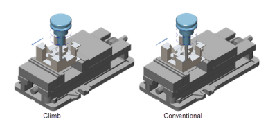
Users can choose between the new climb or conventional cutting methods and define the contact point between the tool and the workpiece, e.g. in the middle of the flute. This is relevant for non-ball cutters like chamfer mills where careful control over the cutting conditions creates chamfered edges with a high quality finish.
The new horizontal stepovers for rotary wall finishing users make it possible to add cuts in the shallow, cylindrical areas for a homogeneous finish across the workpiece, eliminating the need for consecutive finishing toolpaths.
To speed up the programing of roughing and finishing cycles, 3D containments are now generated automatically from the selected floor surface.
Applying tilting during the lead-in ramps and defining the start points and tool engagement offers enhanced control over the roughing and finishing process.
6 Axis Profiling
The ModuleWorks 5 axis tilting strategies are now available for 6 axis profiling to extend the capabilities of 6 axis robotic applications.
The image shows an example application of the new tilting strategies.
A Unified Solution for 3 Axis Machining
The new unified solution is designed for improved performance and reliability with consistent features available across all cycles. It also provides a simple bridge to 3+2 axis and 5 axis machining and enables ModuleWorks to rapidly develop and deploy new 3 axis features.
2D Contouring and Profiling
The new 2 axis contouring cycle takes a simplified and generic 2D polyline as input and generates a toolpath suitable for plasma and laser cutting processes with specific lead in and lead out motions and parameters to control the feed rate, plasma flow rate and pierce point behaviour.
For 2D profiling it is now possible to select an array of curves in a single operation and change the offsets, draft angles, cutting sides and machining heights for each curve. This eliminates the need to create multiple operations for individual curves.
Laser Aided Manufacturing
Multi-axis additive toolpaths traverse numerous deposition layers that build up the part or fill a cavity inside a part. The properties of each deposition layer depend on the type of process being used, which means parameters such as the step over or depth can vary with each new layer. To provide more process flexibility and control, users can now select a polyline to define the start point of each layer.
CAM Utilities - Mesh Tool Kit
A newly added function determines the triangulation tolerance of a given mesh with respect to the input surface. This is useful for validating a toolpath calculation input mesh.
It works like this: Most toolpaths are based on meshes, and the cut tolerance defines the accuracy of the toolpath for a given mesh. If the mesh is not triangulated correctly, the cut tolerance is no longer valid. With this new feature, the Mesh Tool Kit can now validate the mesh quality with respect to the cut tolerance.
Contact Details
Related Glossary Terms
- computer-aided manufacturing ( CAM)
computer-aided manufacturing ( CAM)
Use of computers to control machining and manufacturing processes.
- feed
feed
Rate of change of position of the tool as a whole, relative to the workpiece while cutting.
- profiling
profiling
Machining vertical edges of workpieces having irregular contours; normally performed with an endmill in a vertical spindle on a milling machine or with a profiler, following a pattern. See mill, milling machine.
- tolerance
tolerance
Minimum and maximum amount a workpiece dimension is allowed to vary from a set standard and still be acceptable.
- toolpath( cutter path)
toolpath( cutter path)
2-D or 3-D path generated by program code or a CAM system and followed by tool when machining a part.


