CAM Software with Turning Cycle that Includes B-Axis Movements
CAM Software with Turning Cycle that Includes B-Axis Movements
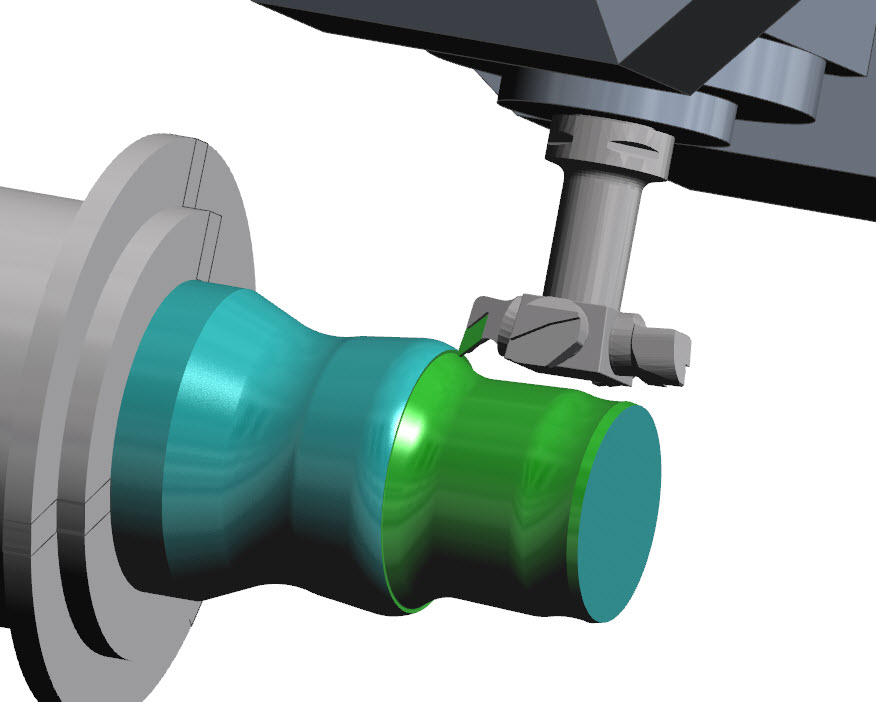
The latest release of Edgecam software introduces a new turning cycle that includes B-axis movements while machining on a turning center. This new feature in Edgecam 2017 R2 allows greater accessibility when machining complex profiles, by dynamically positioning the insert.

The latest release of Edgecam software introduces a new turning cycle that includes B-axis movements while machining on a turning center. This new feature in Edgecam 2017 R2 allows greater accessibility when machining complex profiles, by dynamically positioning the insert.
Edgecam Brand Manager John Buehler says the toolholder is gouge-protected during deployment, and the user can have additional control over the toolpath by deploying over-ride angles. "This new cycle can be used with all types of turning tools, and for both roughing and finishing operations."
There are about 20 items of new and enhanced functionality in Edgecam 2017 R2, from the Vero Software stable, covering turning, milling, simulation and wire EDM.
Amongst the updates, when using the Fixture Database it is now possible to measure fixtures and other workholding devices. "It's essential to be able to accurately measure the exact position and size of the fixture, as well as clarifying its relationship to components, stock and any other workholders," explains Buehler.
Regarding Feature Finding, information transmitted by CadLink has been enhanced where "Limits and Fit" data is now passed to the Edgecam feature. This support covers CREO, SolidWorks and Inventor files. As well as showing the characteristic of the feature, this information also empowers strategy manager authors to capture and use the data when creating machining routines.
The Live Job Reports function was previously run as a windows service. Edgecam 2017 R2 swaps it to a desktop application, improving reliability when altering user profiles.
"With so many software tools available in Edgecam it can sometimes be difficult to judge which commands to permanently fix on the interface, but the latest release overcomes this with a new Quick Search function," says Buehler. "Less common functionality can be easily located and deployed by simply searching the command library."
The 2017 R2 release continues Edgecam's evolution of updating cycle dialogs with pictures and context-sensitive help. "In this instance, Slot Milling, Project Flow Curves and Project Circular Pattern cycles have all been updated. This feature not only assists regular users to easily interpret infrequently used commands, but it also aids less familiar users to quickly understand fundamental functionality."
The Inspection Module offers what Buehler describes as "unparalleled ease of use and sophisticated probe path generation" for both in-process and end-item part inspection. "It provides a robust environment for on-machine probing, supporting a wide array of feature types, path creation and report generation." Responding to the growing need for offline inspection and probing, Edgecam caters to CAM programmers, and utilizes CAD models. Using a set of easy-to-use commands, the user creates a set of inspection features that are then converted into a toolpath and simulated. This means the machine code macros are created via Edgecam's postprocessor.
The Machine Simulator benefits from two additional enhancements. The ability to pick the target component while using View Comparison was introduced in the previous release, and has now been enhanced so that users can now opt for "All components," which is especially useful when working with numerous parts on a multiple-loaded fixture.
And secondly, a quicker, more convenient way of rewinding the toolpaths has been introduced when exiting Machine Simulator: rather than using the traditional menu option, users can now simply hold down the shift key.
Both the Roughing and Hole Drill cycles have been upgraded to be more consistent with existing functionality – namely when roughing to full depth, users no longer need to state a 'cut increment' value. In previous releases, it was necessary to provide a figure.
Similar to the Roughing cycle, when set to 'Use Current Stock,' the 2017 R2 Hole cycle no longer requires a Z Level value, as the system automatically detects the start position for the toolpath.
Finally, for wire EDM users, numerous enhancements have been made to the Machine Configurator. Support for multiple versions of EDM Expert is now available, and a new technology settings have been added, allowing cycles to automatically switch to the appropriate EDM Expert technology page.
The ACVision and Excetek postprocessors now have more options, giving greater user control.
And, lastly, the Tagging functions now allow a non-parallel movement when exiting a machining path. "This assists with better code output and allows a constant tag width along the entire part," says Buehler.


