CAMWorks 2017
CAMWorks 2017
Geometric Americas Inc. released CAMWorks 2017 with significant additions to the software focusing on customer needs and worldwide manufacturing initiatives, such as Smart Manufacturing and Industrie 4.0. The new capabilities in CAMWorks 2017 are a result of more than 60 customer-driven enhancements.
Geometric Americas Inc. released CAMWorks 2017 with significant additions to the software focusing on customer needs and worldwide manufacturing initiatives, such as Smart Manufacturing and Industrie 4.0. The new capabilities in CAMWorks 2017 are a result of more than 60 customer-driven enhancements.
"The additions to CAMWorks 2017 reinforce our vision of providing customers with a level of CNC programming automation well beyond the industry norm. As the design and manufacturing world continues to adopt SOLIDWORKS® Model Based Definition (MBD), Product Manufacturing Information (PMI), and worldwide initiatives like Smart Manufacturing and industry 4.0, CAMWorks will lead in providing faster Design-to-Manufacturing solutions," said Jim Foster, CAMWorks vice president channel sales and marketing.
Some of the most significant enhancements to CAMWorks 2017 include:
Tolerance Based Machining (TBM) – Uses tolerances and non-geometric data in a 3D CAD model to select optimal machining strategies and create toolpaths automatically. CAMWorks unique TBM capability leverages SOLIDWORKS MBD and DimXpert information to read annotations from a SOLIDWORKS 3D model and use the annotations to, automatically selects the tools, feed and speed required to develop optimal toolpaths. TBM can increase productivity by as much as 70% or more over traditional CNC programming methods while providing the ability to capture and re-use best practices. It also improves quality by automatically selecting the best machining strategy to meet the required quality requirements, according to the company.
CAMWorks High Speed Machining, VoluMill Milling Advisor – Provides recommended feed and speed parameters to maximize the performance of VoluMill high-speed machining.
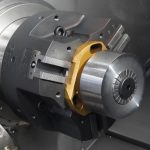
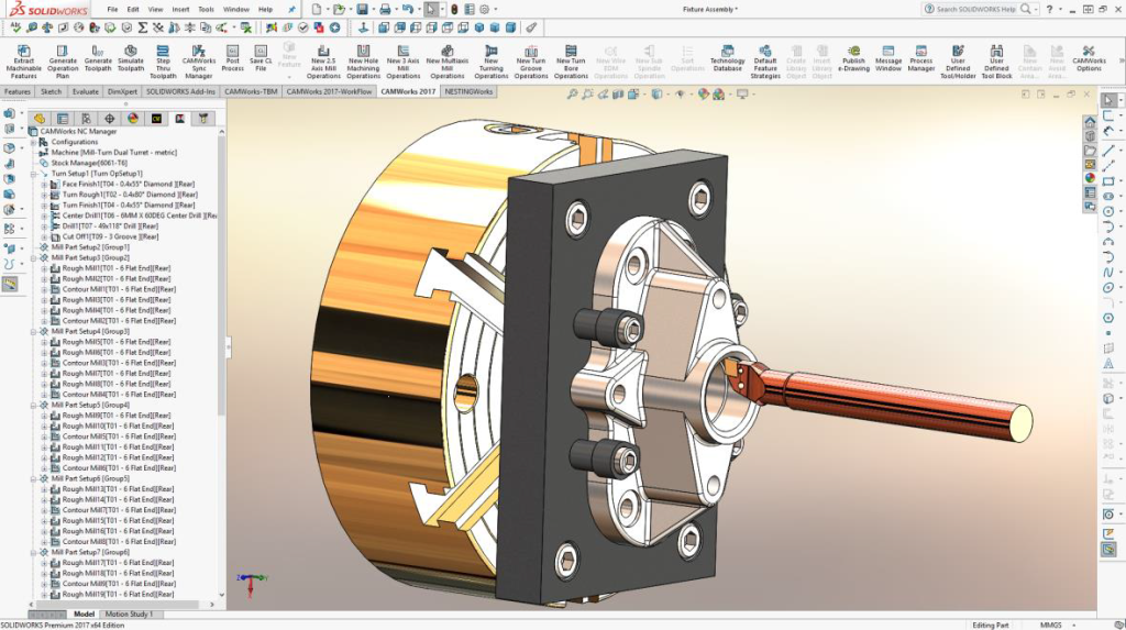
Chuck and Fixture Definition – Provides the ability to use chucks and fixtures designed using SOLIDWORKS parts and assemblies or STL files for toolpath simulation and collision detection in mill-turn and turning. The chucks and fixtures can be moved or rotated in x, y, and z directions with respect to the Fixture Coordinate System (FCS) of the current part, ensuring that the chuck or fixture is properly aligned with the current part. SOLIDWORKS configurations of the chucks and fixtures are also supported.
3D Interconnect in SOLIDWORKS and CAMWorks Solids – Provides a continuous path of associativity from 3D model changes in all leading 3D CAD formats through automatic updating of toolpaths that dramatically speeds up re-programming as parts change.
Tighter integration with SOLIDWORKS ensures that the design and manufacturing models are one and the same. SOLIDWORKS and CAMWorks are fully associative in all aspects including API Automation with SOLIDWORKS partner products such as DriveWorks, Configurations, MBD, and DimXpert annotations, meaning that any change made to a 3D model in SOLIDWORKS on the design side will automatically be reflected in CAMWorks on the manufacturing side. With this strong connection, machining strategies in CAMWorks are based on annotations from the MBD data provided by DimXpert in SOLIDWORKS. 3D Interconnect in SOLIDWORKS provides associativity to all major CAD formats, from geometry level changes through toolpath generation, dramatically reducing CNC reprogramming efforts.