Enhanced Parallel Finishing toolpath in WORKNC 2021
Enhanced Parallel Finishing toolpath in WORKNC 2021
Another important feature in the latest release of the software is the New Part centering/probing function, which generates pointset nodes for any inspection machine or direct CNC part inspection on a milling machine. Additionally, a new Probe Inspect command creates and exports control points in the CAM project to feed a probing system. There are also specific improvements to part centering tailored for CNC machines with table palletization. n

"On average, twice as fast. For some projects, four times faster."
Those figures have been recorded for the enhanced Parallel Finishing toolpath in WORKNC 2021, which lets manufacturers use high-speed cutters of any shape, especially circle-segment tools such as barrel, lens and oval cutters.
WORKNC International Technical Manager Jean-Louis Humbert says, "This strategy is now on average twice as fast as the previous equivalents, Planar Finishing and Z-Level finishing. In certain projects, the calculation time difference was four times faster."
Another important feature in the latest release of the software is the New Part centering/probing function, which generates pointset nodes for any inspection machine or direct CNC part inspection on a milling machine. Additionally, a new Probe Inspect command creates and exports control points in the CAM project to feed a probing system. There are also specific improvements to part centering tailored for CNC machines with table palletization.
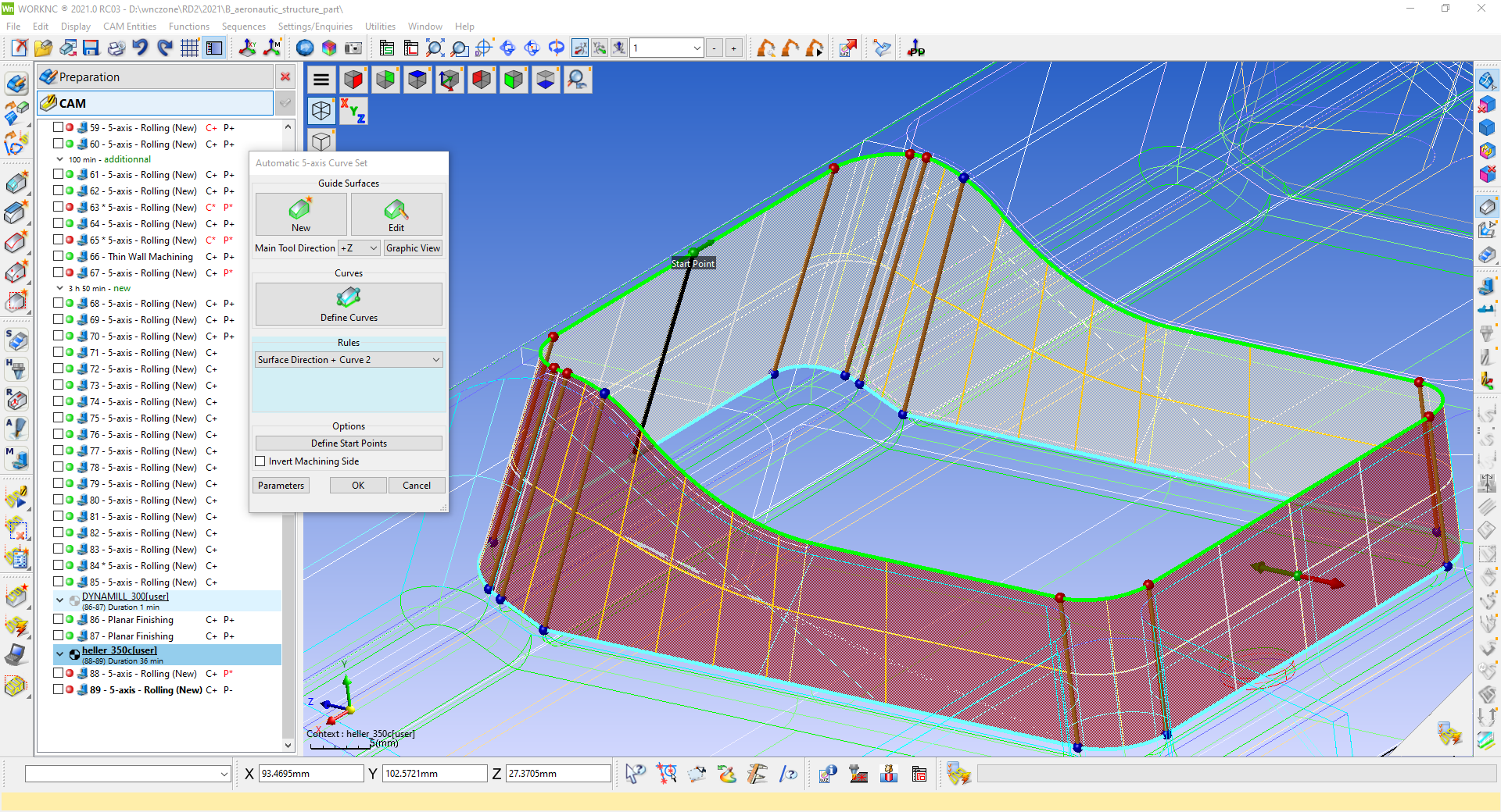
The latest release builds on the popular fully-automatic 5-axis curve creation by splitting the steps when more complex curves are required. It also enhances the synchronization capabilities between each curve's bottom and top limits.
Improvements to corner finishing with 5-axis rolling include being able to improve surface quality by using a cutting tool's larger circle segment. "This 5-axis strategy can now change the contact point on the tool, ensuring optimal corner finishing with the tip of an oval tool," Humbert says.
A new strategy – 5-Axis ISO Guiding – not only guides the toolpath by curves, but also by an underlying drive surface. It supports profiled cutters with advanced toolform technology, and new 5-axis blade finishing functionality allows profile cutter management based on new algorithms.
New items of functionality in WORKNC Designer – the specialist CAD-for-CAM 3D modelling module – include eight dedicated advanced analysis functions for interrogating, analyzing and validating CAD models: Compare, Draft Analysis, Edge Analysis, Altitude Analysis, Curvature Analysis, Face area Analysis, Thickness and Face type.
WORKNC Designer's Reverse Engineering module allows imported scan data, either from files or directly by connecting to Hexagon scanners, to be converted into a refined mesh. The mesh data can then be used as it is, or as a reference for curve and surface creation, enabling mesh models to be fully reverse engineered to complete CAD or convergent models.


