GibbsCAM 2015 Software for Production Machining

September 01, 2015

3D Systems has begun shipping the latest version of GibbsCAM, its software for production machining. This comprehensive update to 3DS' industry-leading software incorporates an all-new Universal Kinematic Machine (UKM) engine that further simplifies CNC programming. The release also includes multiple enhancements that extend capabilities and accommodate new machines of all configurations.
As an integral component of 3DS' design-to-manufacturing digital thread, facilitating cross-technology manufacturing between additive and subtractive methods, GibbsCAM enables improved production efficiency and greater profitability. Developed for ease-of-use, GibbsCAM empowers numerical control programmers and machinists, with solid modeling, 2- through 5-axis milling, high speed machining, mill/turn, Swiss, multi-task machining and wire-EDM capabilities.

"We are committed to providing 3D digital design and fabrication solutions that enable our customers to be more productive and competitive," said Ilan Erez, Vice President, co-Chief Operating Officer and CFO, Software Products, 3DS. "With the recent addition of GibbsCAM to the 3DS digital manufacturing thread portfolio, our customers can now enjoy the ability to use both subtractive and additive manufacturing to achieve the highest productivity possible. Manufacturers can use the two technologies in tandem, printing a metal part and then using a milling machine to achieve the required surface finish, for example. It's a perfect fit.

"With the new release of GibbsCAM 2015 we enable our customers to program any machine with a single program and a single interface," continued Erez. "The new features and enhancements in GibbsCAM 2015 are designed to save time in programming, provide more flexibility in selecting and using tools, and make toolpath verification and machine simulation more accurate and efficient."

Some of the new features in GibbsCAM 2015 include:

New tooling functions and capabilities that extend the ability to define, use and simulate tools, with new icons and dynamic 3D viewing of tools and tool holders. Support for straight, tapered and stepped shanks was extended to all mill tools, while new mill and lathe tool types are also introduced, including 3D form tools and 75° Diamond (ISO E-style) lathe tools.

Numerous enhancements for holemaking that include additional support for hole features from CAD systems and full associativity for hole features from Autodesk Inventor, CATIA v5, Solid Edge and SolidWorks. New is the Hole Editor for editing hole features, including compound holes, which are supported with multiple straight, tapered and threaded segments. In addition, feature recognition has been enhanced, and the 5-axis drilling interface has been streamlined. These features simplify holemaking operations and make the programming process faster.

Intermediate tooling support for multi-task machining, which makes tooling more manageable, simulation more accurate, and programming easier, with more accurate placement and orientation of tools. Additions include a tool block library and support for tool blocks, such as adapter blocks, holders for tool holders, right-angle and adjustable heads, and flash tooling. A fixture library and support for fixtures (chucks, tailstocks, steady rests and other work holding devices) are included.

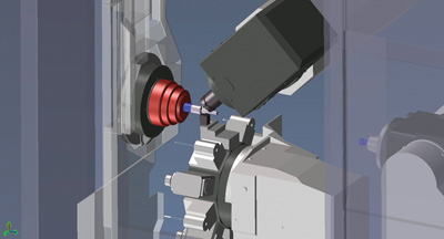
Machine simulation, which is greatly improved as a result of UKM, intermediate tooling support, and an improved rendering palette. Rendering is more accurate and efficient, displaying intermediate tooling for a more complete simulation of all moving components. Customized monitoring of key conditions is enabled with a new Stops and Watches feature. Combined, these additions make the programming-through-simulation process faster and more accurate.

Integration with Sandvik Coromant's Adveon tool library, which enables importing tools from Sandvik and ISO 13399 compliant systems to make a standard library available at any time, simplifying tool definition and tooling-data management. This also allows a shop to build, save and reuse a library, and link tools and tool assemblies to parts and processes, enabling faster reuse of a program for a subsequent part run, and faster updating when parts change.

Related Glossary Terms

  • computer numerical control ( CNC)

    computer numerical control ( CNC)

    Microprocessor-based controller dedicated to a machine tool that permits the creation or modification of parts. Programmed numerical control activates the machine’s servos and spindle drives and controls the various machining operations. See DNC, direct numerical control; NC, numerical control.

  • computer-aided design ( CAD)

    computer-aided design ( CAD)

    Product-design functions performed with the help of computers and special software.

  • fixture

    fixture

    Device, often made in-house, that holds a specific workpiece. See jig; modular fixturing.

  • flash

    flash

    Thin web or film of metal on a casting that occurs at die partings and around air vents and movable cores. This excess metal is due to necessary working and operating clearances in a die. Flash also is the excess material squeezed out of the cavity as a compression mold closes or as pressure is applied to the cavity.

  • gang cutting ( milling)

    gang cutting ( milling)

    Machining with several cutters mounted on a single arbor, generally for simultaneous cutting.

  • lathe

    lathe

    Turning machine capable of sawing, milling, grinding, gear-cutting, drilling, reaming, boring, threading, facing, chamfering, grooving, knurling, spinning, parting, necking, taper-cutting, and cam- and eccentric-cutting, as well as step- and straight-turning. Comes in a variety of forms, ranging from manual to semiautomatic to fully automatic, with major types being engine lathes, turning and contouring lathes, turret lathes and numerical-control lathes. The engine lathe consists of a headstock and spindle, tailstock, bed, carriage (complete with apron) and cross slides. Features include gear- (speed) and feed-selector levers, toolpost, compound rest, lead screw and reversing lead screw, threading dial and rapid-traverse lever. Special lathe types include through-the-spindle, camshaft and crankshaft, brake drum and rotor, spinning and gun-barrel machines. Toolroom and bench lathes are used for precision work; the former for tool-and-die work and similar tasks, the latter for small workpieces (instruments, watches), normally without a power feed. Models are typically designated according to their “swing,” or the largest-diameter workpiece that can be rotated; bed length, or the distance between centers; and horsepower generated. See turning machine.

  • lathe bit ( lathe tool)

    lathe bit ( lathe tool)

    Cutting tool for lathes and other turning machines. Normally a single-point cutting tool, square in cross section and ground to a shape suitable for the material and task. Intended for simple metal removal, threading, slotting or other internal or external cutting jobs. Clearance to prevent rubbing is provided by grinding back rake, side rake, end relief and side relief, as well as side- and end-cutting edges.

  • milling

    milling

    Machining operation in which metal or other material is removed by applying power to a rotating cutter. In vertical milling, the cutting tool is mounted vertically on the spindle. In horizontal milling, the cutting tool is mounted horizontally, either directly on the spindle or on an arbor. Horizontal milling is further broken down into conventional milling, where the cutter rotates opposite the direction of feed, or “up” into the workpiece; and climb milling, where the cutter rotates in the direction of feed, or “down” into the workpiece. Milling operations include plane or surface milling, endmilling, facemilling, angle milling, form milling and profiling.

  • milling machine ( mill)

    milling machine ( mill)

    Runs endmills and arbor-mounted milling cutters. Features include a head with a spindle that drives the cutters; a column, knee and table that provide motion in the three Cartesian axes; and a base that supports the components and houses the cutting-fluid pump and reservoir. The work is mounted on the table and fed into the rotating cutter or endmill to accomplish the milling steps; vertical milling machines also feed endmills into the work by means of a spindle-mounted quill. Models range from small manual machines to big bed-type and duplex mills. All take one of three basic forms: vertical, horizontal or convertible horizontal/vertical. Vertical machines may be knee-type (the table is mounted on a knee that can be elevated) or bed-type (the table is securely supported and only moves horizontally). In general, horizontal machines are bigger and more powerful, while vertical machines are lighter but more versatile and easier to set up and operate.

  • milling machine ( mill)2

    milling machine ( mill)

    Runs endmills and arbor-mounted milling cutters. Features include a head with a spindle that drives the cutters; a column, knee and table that provide motion in the three Cartesian axes; and a base that supports the components and houses the cutting-fluid pump and reservoir. The work is mounted on the table and fed into the rotating cutter or endmill to accomplish the milling steps; vertical milling machines also feed endmills into the work by means of a spindle-mounted quill. Models range from small manual machines to big bed-type and duplex mills. All take one of three basic forms: vertical, horizontal or convertible horizontal/vertical. Vertical machines may be knee-type (the table is mounted on a knee that can be elevated) or bed-type (the table is securely supported and only moves horizontally). In general, horizontal machines are bigger and more powerful, while vertical machines are lighter but more versatile and easier to set up and operate.

  • numerical control ( NC)

    numerical control ( NC)

    Any controlled equipment that allows an operator to program its movement by entering a series of coded numbers and symbols. See CNC, computer numerical control; DNC, direct numerical control.

  • toolpath( cutter path)

    toolpath( cutter path)

    2-D or 3-D path generated by program code or a CAM system and followed by tool when machining a part.

PRODUCTS

11/20/2024
Jorgensen Conveyor and Filtration Solutions, Mequon, Wisconsin, highlighted its distinctive…

10/23/2024
TIN Coated Thread Gages have high dimensionally stable HSS construction with TIN coating that…

10/23/2024
The Starrett AVR400 offers full CNC capabilities including X-Y-Z positioning and comprehensive zoom…