Mastercam 2018 CAM Software
Mastercam 2018 CAM Software
CNC Software announces the release of Mastercam 2018. Mastercam 2018 brings a new suite of programming tools focused on delivering speed, automation and efficiency for all machining jobs. Mastercam 2018 offers new 2D/3D Milling features, Design improvements, and powerful turning and Mill-Turn enhancements.
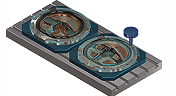
CNC Software announces the release of Mastercam 2018. Mastercam 2018 brings a new suite of programming tools focused on delivering speed, automation and efficiency for all machining jobs. Mastercam 2018 offers new 2D/3D Milling features, Design improvements, and powerful turning and Mill-Turn enhancements.
Stock awareness has been added to select 2D toolpaths and allows tool motion on the top, bottom, or both values of the stock. This provides a safer and more optimized tool motion. You can also optimize finish passes based on your rough stock, giving you more efficient and safer tool motion. The workflow for all 3D high-speed toolpaths has been streamlined and gives you fine control over exactly where to cut. High-speed hybrid toolpaths now offer smoothing controls and deliver a finer finish, requiring less handwork.
If you work with stringy materials such as aluminum or plastic, Mastercam's new Chip Break control prevents problems by allowing you to set length and time conditions, retract, and dwell options. Mill-Turn machine definitions now contain tailstock and quill components, tailored to your machine.
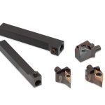
Exclusive to Mastercam, a new set of turning strategies automate toolpath generation and support for Sandvik Coromant CoroTurn Prime inserts and PrimeTurning method. PrimeTurning provides superior metal-removal rate, productivity gains of over 50 percent and increased tool life in a variety of materials.
Shops can model their own designs, but they also get in models that need to be corrected or prepped for machining. Mastercam's CAD functions are designed for the machinist. Angle Sweep improves the creation of more complex wireframe functions and when creating or editing primitives, there are now on-screen sweep and rotate controls which can snap to the AutoCursor positions of existing entities. To make Roll and Unroll results easier to predict, Seam Control lets you visually rotate a seam to see how geometry will respond, as well as snap to AutoCursor positions. Hole Axis makes it easier to work with a large number of holes, especially holes with matching diameters that are selected as a group.
Also available in the Mastercam 2018 release is:
- My Mastercam gives you access to your profile, Mastercam's social media outlets, your Reseller information, the Mastercam Forum, and other helpful information.
- Streamlined workflow with improved plane management, level and geometry control, toolpath analysis and more.
- Model Prep and Solid Model enhancements such as Multiple Undo/Redo for up to twenty-five functions and Solid Sweep has more options and controls than ever.
- The Collision Control and the Multiaxis Link Safety Zone pages for Multiaxis toolpaths have been redesigned for Mastercam 2018.
- Common direction has been added to the Tool Axis Control page for Multiaxis toolpaths and keeps the tool at a uniform tilt angle to reduce tool and machine motion.
- And many other productivity improvements across the entire product.


