ModuleWorks Optics Kernel
ModuleWorks Optics Kernel
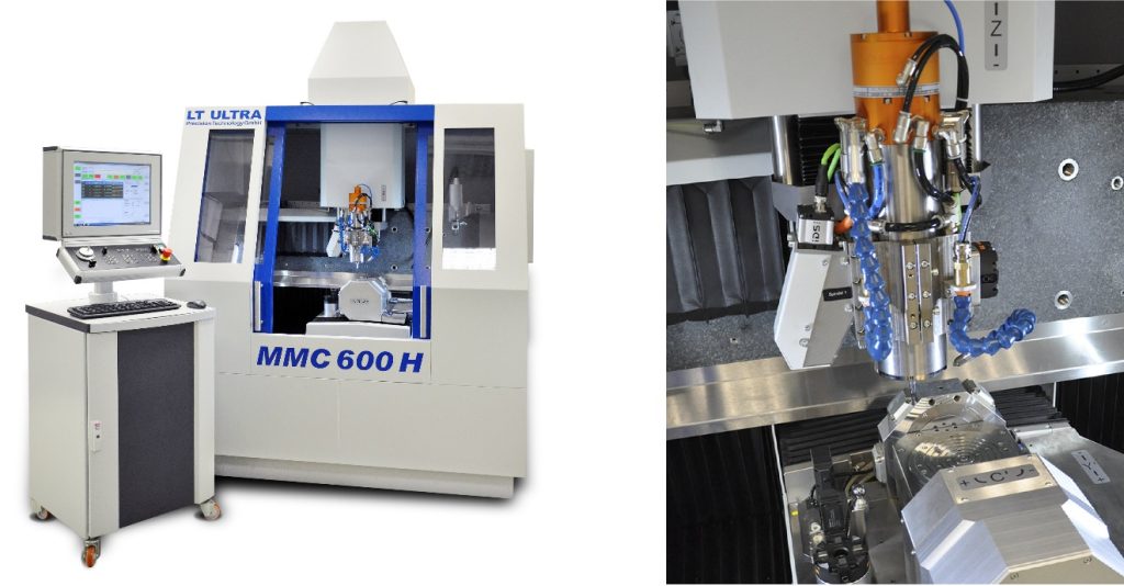
The ModuleWorks optics kernel has been developed to meet the growing demand for machining increasingly complex free-form geometries with a precision in the nm range. Integrated into the LT CAM product line, it enables LT Ultra to offer flexible solutions for a diverse range of ultra-precision machining applications with automatic toolpath calculation from point clouds, CAD models and analytical functions as well as corrections based on real measurement data.

CAD/CAM software specialists ModuleWorks and LT Ultra, specialists for ultra-precision technology, have collaborated on a software solution for ultra-precision milling and turning. Built upon the ModuleWorks 6-axis optics kernel, the new software enhances LT Ultra's machining platforms with automated workflows for manufacturing diverse parts with nanometer precision.
The ModuleWorks optics kernel has been developed to meet the growing demand for machining increasingly complex free-form geometries with a precision in the nm range. Integrated into the LT CAM product line, it enables LT Ultra to offer flexible solutions for a diverse range of ultra-precision machining applications with automatic toolpath calculation from point clouds, CAD models and analytical functions as well as corrections based on real measurement data. The calculated toolpaths are automatically available for full 3D machining simulation and output via a high-performance CNC posting framework that uses multi-threading for fast generation of large NC programs (up to 50k points per second).
"The ModuleWorks optics kernel allows the full potential of machines to be exploited. The exceptional calculation precision in the nm range and flexible adaptation to our series and custom machines are outstanding. For our customers as well as our own contract manufacturing, we have developed a solution in close cooperation with ModuleWorks that prepares us for the future of ultra-precision machining," says Dr. Kurt Haskic, Head of Research at LT Ultra.
"Working in close cooperation is the best way to get the most out of our combined technologies and it's great to see how our optics kernel helps our customers to build innovative, state-of-the-art solutions at the forefront of ultra-precision machining" says Lothar Glasmacher, Head of Business Additive and Process Technology at ModuleWorks.


