MSR TwinDrive
MSR TwinDrive
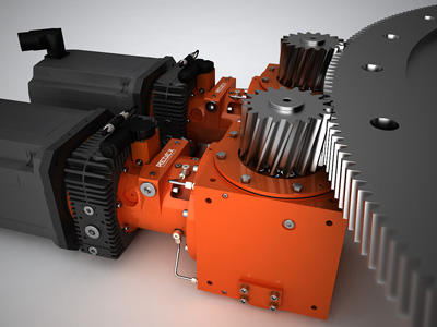
The latest version of REDEX' MSR TwinDrive dramatically simplifies the mechanical transmission system on large vertical lathes.

The latest version of REDEX' MSR TwinDrive dramatically simplifies the mechanical transmission system on large vertical lathes. As a result, the design of turning tables becomes much easier while improving the precision and making the machine more compact. REDEX has once again produced innovative products and solutions that offer machine builders cutting-edge designs that feature easy use and maintenance.
REDEX has once again enhanced its solutions for turning tables on large vertical lathes. The latest MSR drive designs have been refined using the newest generation of drive and control systems (i.e. from Siemens CNC or FANUC). The MSR drive is composed of two identical gearboxes (TwinDrive system), sharing the driving torque (50 percent-50 percent) during turning operations. With the help of the CNC system which manages the motor preload torque, the system is able to cancel 100 percent of backlash. In addition, MSR exclusive features enable a very accurate positioning level. Thus, it allows the execution of additional functions on the C-axis, without any additional mechanical devices. For instance, top accuracy is kept during milling operations with one motor driving and the other motor braking.
REDEX provides the unique commercial solution for turning and milling drives in the machine-tool market. Before MSR, turning table manufacturers used 2 different types of drives when a C axis was needed: a main drive for turning operations driven by a big spindle motor and a feed-preloaded gearbox to cancel the backlash during C-axis mode that needed to be clutched and unclutched to the crown. In addition, the main drive need to be shifted to neutral ratio.
The MSR drive solution from REDEX reportedly dramatically simplifies the design of turning table mechanical transmission systems. It eliminates the need for developing a complex and expensive gearbox for the C-axis, including a complicated system of clutching/unclutching, according to the company. A solution with two motors is less expensive and easier to manage. In comparison to high-duty turning tables used in conventional configurations that require a 160kW motor, the MSR uses two 80kW motors, which are more standard and less expensive (despite the fact that there are two of them). When the diameter of the chuck or part to machine is large, conventional home-made kinematics consisted of using a different stage ratio of 1/1, which resulted in high costs and loss of efficiency. MSR kinematics allow the drive to be placed right under the chuck directly meshing with the crown. Spare parts management is simplified with the use of a smaller motor. Furthermore, there is no need to manage the C-axis gearbox manufacturing with all its components.
For this new MSR drive solution, developed as a turnkey system by REDEX, the latest generation of MSD two-speed gearbox is combined with the improved version of cubic R Series right angle bevel gearbox. The design upgrade includes a new and more compact and reliable speed changer as well as a new lubrication arrangement. The external appearance has also been improved as required for high-tech machine-tool component design. Supplied as a self contained sub-assembly, this integrated and compact system is ready to be implemented. Depending on machine arrangement, OEM can use the bevel box as an option.
The new range improves features of the 4 sizes, MSR330- MSR640- MSR650- MSR660 with torque capacity at pinion from 2000/4000Nm (2 x 40Kw motors) up to 9000/18000Nm (2 x 100Kw motors) with 3 possible ratio combinations of 7.66&2, 9.88&2, 11.49&3. This solution, combined with pinion/ring ratio of about 10 to 15 offers turn table torques from 20 0000Nm up to 270 000Nm and global ratios (gearbox + ring gear) of 77/20 and 172/45.


