PartMaker Version 2011
PartMaker Version 2011
PartMaker Inc., a division of Delcam Plc, has released PartMaker Version 2011, the latest version of PartMaker Software for programming CNC Mills, Lathes, WireEDM, Turn-Mill Centers and Swiss-type Machines.
PartMaker Inc., a division of Delcam Plc, has released PartMaker Version 2011, the latest version of PartMaker Software for programming CNC Mills, Lathes, WireEDM, Turn-Mill Centers and Swiss-type machines. Major highlights of PartMaker Version 2011, include more powerful milling functionality, an optional module for 3D design and model repair, a more flexible tooling library, improved programming and simulation of Bar-Fed Mills, more vivid set-up documentation and a host of additional productivity enhancements.
"PartMaker Version 2011 further demonstrates the accelerated pace of development PartMaker has undergone since its acquisition by Delcam four years ago," says PartMaker Inc. division President Hanan Fishman. "Since joining Delcam, the functionality, capability and power of the PartMaker CAM software suite has grown massively by taking advantage of Delcam's extensive development resources. Delcam's world wide team of over 225 developers is the CAM software industry's largest development team. Multi-axis milling functionality that has taken Delcam many, many man years to develop is being added to PartMaker at a rapid pace and reduced cost, which provides a major benefit to the product's end users. PartMaker Version 2011 also has an optional module for 3D design, providing PartMaker users best in breed software for both CNC programming and addressing 'design for manufacturability' issues."
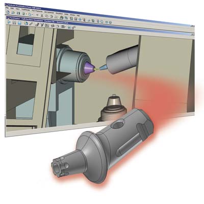
PartMaker Version 2011 features the PowerSHAPE Companion for PartMaker, an optional module to allow you to design 3D models, repair poor quality 3D data and modify 3D geometry to improve "Design for Manufacturability" (DFM). This new optional module features the powerful "Solid Doctor" utility, allowing you to read and repair models from all sources and tackle the common problems that can be found when translating low-precision and incomplete 3D data by detecting and repairing faults in engineering models and generating a valid, high-precision solid model ready for programming in PartMaker.
PartMaker Version 2011 lets you manage your tool inventory in a new, more universal manner through the use of "Master Tools Databases." Master Tools Databases can be edited, manipulated and stored through external database programs like Microsoft Excel and individual tools can be quickly imported for specific jobs. This new approach makes programming more productive because it allows you to quickly choose tools created previously faster than before. It also allows you to reduce the size of a given tool library for a particular programming job. Tools can be interchanged between PartMaker's Tool Files and your Master Tools Database. This new feature will also allow individuals at your company without access to or familiarity with PartMaker to manage the tool inventory available to your CNC programmers.
Bar-Fed Mills are a new breed of machine tool technology that is growing more popular for the production of small, complex parts for such applications as medical device, aerospace, fluid power and any other industry that requires complex small parts. In many ways, these machines represent the future of complex, low volume, small parts manufacturing. With Version 2011, PartMaker aims to establish itself as the market leading system for automating the programming of Bar-Fed Mills by introducing a number of new features for handling the unique programming issues presented by these machines. PartMaker Version 2011 simulates the unique architectures and machine kinematics of Bar-Fed mills in its 3D simulation module and supports the Bar-Fed mill offerings with robust post processors and vivid simulation of such machines from leading builders like Willemin-Macodel, Bumotec, Chiron, Mazak, Star and others.
PartMaker Version 2011 features a host of improvements to the PartMaker Documentation Wizard (PDW) module including a number of new standard set-up sheet templates as well as the ability to automatically create "mid process" set-up sheets. Mid process set-up sheets display a picture of the part being machined at each step in the machining process as well as a graphical view of the tool used in that process. Such set-up sheets can be a great way to communicate to shop floor personnel exactly how a part should be processed and can thus speed-up setup time and reduce the possibility of errors.
PartMaker Version 2011 includes a number of enhancements to the software's sophisticated surface machining strategies. These improvements include the addition of a more powerful Surface Swarfing strategy which makes programming swarfing easier and more accurate. The new version also includes the addition of 4-axis Swarfing, which allows you to perform more sophisticated milling on machines only capable of 4-axis cutting, which includes most Swiss-type lathes on the market today.
PartMaker Version 2011 is much faster than previous versions, more than 50 percent faster in many cases. This increase in speed is particularly helpful for the cutting simulation of complex parts with a number of features. The new version also lets you see and verify all your tool paths at once when programming on a solid model. By simply clicking on a hole or profile on a solid model, PartMaker will place you into the profile or hole group where that feature has been defined.
In addition to the improvements mentioned above, PartMaker Version 2011 includes a host of other productivity enhancements including increased input precision, user defined fonts for engraving, more powerful and flexible turning and 2D milling tool paths, improved geometry import functions including support of SolidWorks 2011, DWG import and a free STEP translator, simulation of pinch milling, many enhancements to make the PowerMILL Interface faster and more efficient, new and improved context sensitive help and much, much more.
PartMaker is a Knowledge Based Machining system, allowing it to provide a substantial gain in programming efficiency by remembering the tools, material and process information necessary to machine individual part features. It thus relieves the user from reentering the same features information for subsequent parts. It also improves productivity by placing the emphasis on tool management functions.


