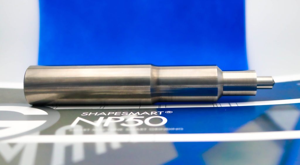
Process for Grinding Large Diameter Carbide Blanks
Process for Grinding Large Diameter Carbide Blanks
Pinch grinding offers highest concentricity particularly on long and thin parts. The rough and finish grinding are performed in one pass. This innovative way to grind roughing and finishing simultaneously eliminates a separate process and reduces cycle time. The machine utilizes two different grinding wheels running on separate spindles and positioned on independently- controlled CNC linear slides.n

Rollomatic, a leading machine tool manufacturer based in Le Landeron, Switzerland, maintains its global leadership position in the field of pinch and peel grinding by spotlighting a new process. Rollomatic is the original inventor of the pinch/peel grinding methodology and stays in the forefront in developing specific processes related to making this type of machine even more productive.
Pinch grinding offers highest concentricity particularly on long and thin parts. The rough and finish grinding are performed in one pass. This innovative way to grind roughing and finishing simultaneously eliminates a separate process and reduces cycle time. The machine utilizes two different grinding wheels running on separate spindles and positioned on independently- controlled CNC linear slides.
Rollomatic improved an advanced process for carbide blank preparation for large blanks of dia. 1" (25.4 mm) with decreased cycle times, based on the latest developments in grinding wheel technology. It covers the these blank preparations and tools:
- Step drill blanks
- Step endmill blanks
- Reverse-shank tools
- Rotary burs
- Tapered endmills
- Back tapering of drills
- Precision punches
- Excellent mirror surface finishes and near-zero TIR for drill margins can be achieved.
- Repeatable process for long-batch production.
- Both grinding stations are equipped with diamond wheels with different grit sizes. One wheel carries out the rough grinding, while the other wheel is for finish grinding. The grit sizes and bond compositions are carefully selected to optimize the surface finish to be achieved, and find the right balance between minimal wheel wear and best cycle time.
- A proprietary process that involves multi-pass grinding and pinch finish grinding is used which has been developed over many years of testing.
- Dimensional tolerances can be maintained over long or short production runs with the help of in-process measurements and automatic compensation for wheel wear and for changes in ambient temperature.
Both grinding spindles are "synchronous direct-drive spindles" with 19 hp peak each. The most important feature of a synchronous motor is that it provides constant speed during its operation and that the torque curve is highly efficient, as per above graph. The rotational force is not reduced with higher RPM's. Synchronous motors always run at a speed equal to their synchronous speed, as opposed to asynchronous motors (induction motors) which always have a lag and are therefore less efficient.
On a test production run, the following results were achieved:
- With the highest achievable material removal rate and a repeatable process on long-batch production grinding, this process outperforms alternative competitive equipment by more than 40%.
- Wheel spindle load on the roughing side (synchronous spindle) was no more than 35%. The limiting factor is the wheel wear and not the machine. The machine will always outperform the wheels.
- The highly efficient synchronous spindles, running at max. 35% power draw or less, do not release any heat into the machine or into the grinding process. This greatly helps with keeping the thermal stability of the machine.
- Synchronous spindles are much quieter even under load compared with induction motors.
- An excellent G-ratio was achieved which is the ratio between the stock removal and the wheel wear volume.
- The wheel wear was manageable. Due to the clean-up pass of the 2nd wheel, the dimensional tolerances of the blank were not affected.
- There were no TIR issues. The mirror surface finishes are exceeding the expectations for a high-performance drill margin.


