Driven to perform
Driven to perform
Tips on choosing driven tools for mill/turn centers.
Where 2-axis CNC lathes were once top dog in most turning departments, mill/turn centers now lead the pack.
With the ability to drill cross-holes, mill complex shapes and sculpt multidimensional surfaces on turned workpieces, CNC lathes with driven, or live, tools are making a big impact on the bottom line of many machine shops, with a commensurate improvement in part quality and delivery time. Despite this obvious benefit, however, driven tools carry the burden of additional tooling costs and a commitment to preventive maintenance of toolholders. This makes it critical for shops to do their homework before embarking on the road to driven tools.
Join the Club
David Fischer, product specialist for Okuma America Corp., Charlotte, N.C., explained that the majority of CNC lathes sold today come with some form of driven-tool capability. Many of these machines offer spindle speeds of 6,000 rpm or higher, with horsepower and torque ratings comparable to small machining centers.
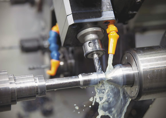
Courtesy of Planet Products
An axial-driven tool and holder from Planet Products mills a keyway on a shaft.
"Compared to 10 years ago, mill/turn centers today have enough power to do some really decent work," Fischer said. "There's also an increased focus on shops looking to avoid moving parts from machine to machine, getting things done in one operation wherever possible. Multifunction, [driven tools] on a standard lathe are a big improvement for them."
Adding that multifunction capability to the purchase of a conventional CNC lathe might be as easy as spending $30,000 for a C-axis spindle option and a live tool-equipped turret. It could also mean investing 10 times that amount or more in a twin-spindle, multiturret monster with more axis letters than a bowl of alphabet soup.
Regardless of how much machine a shop can afford, it's important to remember the additional cash outlay needed to tool that machine. Where a shop might get away with spending a few thousand bucks on some stick tools and ER collet chucks to tool a 2-axis CNC lathe, properly equipping a mill/turn center will cost far more than that.
Fischer advised that, for every live tool station, shops should plan on buying at least three driven toolholders. "It's a good idea to have multiple units—one in the machine making parts, one on the shelf as backup and one at the rebuilder's shop for maintenance." At $3,000 or more for a typical driven toolholder, this means dropping some serious money before the first chip is cut.

Courtesy of Koma Precision
A BMT-style universal angle head from Koma Precision for a Nakamura-Tome mill/turn machine.
Although on a much smaller scale, milling on a lathe means bolting the heart of any toolchanger. See automatic toolchanger." title="CNC machine tool capable of drilling, reaming, tapping, milling and boring. Normally comes with an automatic toolchanger. See automatic toolchanger." aria-label="Glossary: machining center">machining center—the spindle—to a lathe turret. On plain Jane lathes, this turret is nothing but a hunk of iron that indexes and provides a place to mount stationary tool blocks. On live-tool machines, however, the turret and the housing to which it is mounted contain a powerful drive mechanism—typically a planetary gear train and a servo- motor—that engages with a drive tang on the driven toolholder. Attach one of these holders to a live-tool capable turret, load an endmill or other rotary tool and you have a miniature toolchanger. See automatic toolchanger." title="CNC machine tool capable of drilling, reaming, tapping, milling and boring. Normally comes with an automatic toolchanger. See automatic toolchanger." aria-label="Glossary: machining center">machining center.
Tool Bonanza
John Arnestad, tooling manager for Koma Precision Inc., East Windsor, Conn., said various off-the-shelf driven toolholders are available for mill/turn machines. Axial and radial holders mill and drill in the X, Y and Z axes. Universal adjustable angle tools create angled holes and features (see sidebar on page 34). Speed increasers for driving small tools will easily double or triple available speed, and torque increasers cut rpms but increase power for driving larger taps and facemills. On the custom side, the sky's the limit—multispindle tools for faster part production (i.e. center drill, drill and tap on the same station), radial and Y-axis offset heads, hobbing tools for gear production and special tools for application-specific operations.
Aside from the bewildering variety of toolholders, the way they attach to the machine varies considerably as well. "Many machine builders have brand-specific requirements for mounting driven tools to the turrets of their machines," Arnestad explained. "Most of the higher-end machines have proprietary attachments and drive connections. For example, one manufacturer we work with uses either a bolt-mount turret or a VDI-style mounting with a castle nut drive connection. Another uses a bolt-mount turret with a tang drive, while yet another uses a brand-specific VDI connection." [Editor's note: VDI is an acronym for Verein Deutscher Ingenieure, the Society of German Engineers.]

Courtesy of Koma Precision
This Alberti MA-2.5 3U ER-16A collet output tool, distributed in the U.S. by Koma Precision, is used for multitool applications. It can perform center drilling, drilling and tapping on a single turret station.
The bottom line is that machine tool builders have not yet agreed upon a standard for mounting driven toolholders as they have with, for example, CAT 40 milling holders. Check the Web site for most any driven toolholder manufacturer and you'll find a catalog for nearly every builder under the sun. This lack of standardization is a costly headache for any shop owner with multiple makes and models of CNC mill/turn machines. It's a Wild West where every .45 caliber pistol on the street uses a different type of bullet.
It's a tremendous problem for the toolholder manufacturers as well, in that they must design, manufacture and stock thousands of product variations.
"We've got 20,000 live tools in our database," said Preben Hansen, general manager for heimatec Inc., Prospect Heights, Ill. "Each one is unique. For every type of tool, we have to make 50 different back ends."
Hansen added that just getting the information to build those back ends is problematic. "Builders have their own relationships and don't necessarily want new ones, so the specs are seldom available unless you 'belong to the club.' Nor do most tool builders want to reverse engineer the tools—they want to build them to the manufacturer's specifications. Often, we have to work directly with machine distributors and end users to get this information."
Pick One
Despite this complexity, driven toolholders come in two basic mounting styles: VDI and BMT (base-mounted turret). BMT uses four bolts and a set of keyways to locate the holder against the turret face. The driven-tool shank extends into the turret itself, where it engages with a slot in the drive mechanism via a tang or other mechanical coupling. BMT's counterpart, VDI, was one of the industry's first forays into quick-change tooling. It uses a serrated wedge and cam-lock mechanism to pull the toolholder against a locating face on either the periphery of the turret or on its face. Once there, the business end of the VDI holder engages with a splined receiver in the turret's drive mechanism.
Long a darling of European machine tool builders, VDI is ideally suited to driven tools, as the entire tool block can be replaced with a few turns of a single screw. In the U.S., however, VDI has carried a stigma for being less rigid than competing systems, primarily due to its relatively small straight shank when compared to competing holders that use a taper mount.
According to Leigh M. Bickham, product manager for Ramsey, N.J.-based ITI Tooling Co. Inc., a distributor of lathe toolholders, this is an unfair assessment. "Prior to VDI, everything was bolt-on. People began adopting VDI to cut setup time, but somewhere along the way it got a bad rap. Both of our suppliers are German companies and they don't understand why BMT is so popular in the U.S. VDI is not quite as rigid as a bolt-on toolholder, but for the majority of driven-tool applications, it's an excellent choice."
In an attempt to ease these concerns, some machine tool builders offer turrets promising a best-of-both-worlds approach, with VDI holders that bolt to the turret similar to BMT tools. This allows shops to utilize existing VDI tooling while enhancing rigidity.
Even without a VDI turret, however, quick-change tooling is still within reach of driven-tool users. ITI and others offer BMT toolholders equipped with Capto, KM, ABS, HSK or proprietary quick-change systems such as ITI's Varia system. Sadly, most of ITI's customers opt for the tried-and-true ER holder or even one with a Weldon shank, ignoring the benefits of quick-change, according to Bickham. "It's hard to convince anyone to try something new," he said. "Most of the time it's because of the cost. A Capto-style holder, for example, might run 20 percent more than a conventional one. Those who do try quick-change generally come back within a few months to tool up everything that way. They love it."
Bearing Down
The design of driven toolholders varies nearly as much as the machines they mount to. One huge difference of opinion among toolmakers is what bearings to use. Driven tools operate under harsh conditions—high speeds and extreme cutting loads make short work of low-quality or improperly sealed bearings. Some manufacturers utilize permanently sealed, or "greased for life," bearings to deal with these conditions. Others use complex labyrinth or lip seals to keep coolant and chips out of the bearing pack. Those concerned with bearing heat rely on the machine's cutting fluid running through the tool block to cool things down.

Courtesy of heimatec
Complex milling requires a radial milling head, like this one from heimatec, and Y-axis capability.
One unique cooling approach taken by Planet Products Corp., Cincinnati, is running the coolant directly through the bearing pack. General Manager Garth Dexter explained: "It's very simple. We plumb the toolholder in a way that machine coolant continuously lubricates and cools the bearings. Obviously, it's important to bearing life to maintain a clean supply of cutting fluid, so we recommend placing a 10µm or better cartridge filter on the machine's coolant pump. We have one customer that sees over 3,000 hours of hard use between service intervals using this system."
Another unique take on driven-toolholder design is offered by San Antonio, Fla.-based Exsys Tool Inc., which represents the Eppinger brand. Product Support Manager Scott Leitch said torque transfer is critical with driven tooling. "Our tools use what's called a compensating clutch. This helps compensate for any misalignment of the turret, and provides more efficient torque transfer from the drivetrain to the part, allowing the toolholder to engage with the bevel gears on the drive mechanism in a much smoother fashion. It also eliminates the noise and vibration that eat up tooling and put a lot of wear and tear on the drivetrain."
The system can also absorb surprises. "If there's a crash, the clutch is designed to shear away," Leitch said. "This prevents damage to the machine and can be repaired in a few minutes."
Easy Does It
Repair and maintenance should be two key words in the vocabulary of any driven tool user. Glenn Miller, rotary tool repair manager at Minneapolis-based Productivity Inc., provided a number of tips to prolong the life of driven toolholders, starting with the day you take them out of the box.
"In terms of life, we don't see a lot of difference between sealed or unsealed bearings," he said. "What's important is how you run the tools in. Some shops get a brand new tool, throw it in the machine and immediately run it wide open. In 9 months, they're wondering why it's worn out."
Miller added that even with driven tools that are run-in at the factory, the grease tends to settle to one side of the bearing, leaving the opposite side unprotected. And sometimes there's too much grease, which creates excessive heat. "On new toolholders or where they've been sitting for a long time, run the tool at 1,000 rpm for half an hour, then kick it up to 2,000 or so for another half hour. This spreads the grease evenly throughout the bearing."
In a similar vein, keep an eye on high-pressure coolant. "It sounds silly, but quite often the machinist will change setups and the nozzle ends up pointing at the base of the tool, right where the bearing sits," Miller said. "In that situation, it doesn't matter what kind of seal you have—the coolant's going to penetrate it and wash away the grease."
The good news is that, when properly maintained, driven tools often last upwards of 3 to 4, years barring a crash or improper use. "About 2,000 hours is the magic number for preventive maintenance—no different than any other machine tool," Miller said. "You spend a couple hundred bucks to send it out for a thorough cleaning, replace the seals, regrease the bearings and you should be good to go."
Despite the power and rigidity of most mill/turn machines, a good dose of common sense is required when using them. "Just because the live tool has a 10-hp motor attached to it doesn't mean you should expect it to cut like a 10-hp machining center," said Allen Rupert, director of operations for WTO USA Inc., Charlotte N.C. "The first question you have to ask before purchasing any driven toolholder is what you want to do with it. Can you take a 12,000-rpm toolholder designed for high-speed light machining and use it to cut titanium with a 1 " endmill? Sure, but don't expect it to last very long. Every one of these tools has a sweet spot, and you need to find the right tool for your application."
Driven tools are fast becoming the new paradigm in machine shops aiming to reduce operations and handling while increasing part quality and profit. CNC machine tool builders continue to offer more capable mill/turn lathes, and toolmakers are rising to the challenge with durable and accurate driven toolholders. However, the successful use of these accessories often comes down to product knowledge, regular maintenance and plain old shop smarts. CTE
Take a right turn at the milling machine
Mill/turn centers aren't the only machines using driven tools. A number of tooling manufacturers offer angle heads for milling machines, giving shops the ability to machine features on the side of a workpiece without refixturing or indexing the part. Yet David Hartman, product manager for rotary products at Parlec Inc., Fairport N.Y., said there's a big difference between a driven tool and an angle head for a machining center.

Courtesy of Parlec
Milling the inside of a large counterbore might otherwise be impossible without an angle head, such as this one made by Gerardi in Italy and distributed in the U.S. by Parlec under part number F90-16-BT50.
"You buy a mill/turn lathe and the driven toolholders are an extension of that capability—you need them to do the work that machine was designed for," he said. "In the case of an angle head, though, you're not just adding a tool but actually increasing the capability of the machine."
Typically used on 3-axis vertical machining centers, angle heads hold a cutting tool horizontally rather than vertically and use a 90° gear train to spin the tool. This allows shops to drill holes or machine features in the X-Z and Y-Z planes. By rotating the head to a fixed angle in the horizontal plane, angled surfaces and holes can be machined on the workpiece sides. And on larger workpieces, the head can mill inside a pocket, space permitting. Best of all, most angle heads are small enough to be used with an automatic toolchanger, so there's no need to interrupt production with a manual tool change.
"Angle heads are a machining solution," Hartman said. "For shops that have a 3-axis machine but need to do 4-axis work, investing in one of these toolholders makes a lot of sense. Installation is straightforward—a simple stop block is mounted on the spindle head to keep the tool from rotating. This means you can use the same angle head across multiple machines."
Hartman explained that the Parlec by Gerardi Evolution angle heads are modular, so different taper shanks can be accommodated. This means easy repurposing when a new job comes in the door, an important consideration when spending $6,000 or more for a single toolholder.
—K. Hanson
Contributors
Exsys Tool Inc.
(800) 397-9748
www.exsys-tool.com
heimatec Inc.
(847) 749-0633
www.heimatecinc.com
ITI Tooling Co. Inc.
(201) 934-6333
www.ititooling.com
Koma Precision Inc.
(800) 249-5662
www.komaprecision.com
Okuma America Corp.
(704) 588-7000
www.okuma.com
Parlec Inc.
(800) 866-5872
www.parlec.com
Planet Products Corp.
(513) 984-5544
www.planet-products.com
Productivity Inc.
(800) 328-3272
www.productivity.com
WTO USA Inc.
(704) 714-7765
www.wto-usa.com
SaveSave


