When working in a shop, a time will come when you’ll be obliged to attempt a technique or cutting routine you’ve never tried before. Those times can be a little unnerving. Most customers and employers want positive results immediately, which does not leave much room for error.
Following are some tips and unusual methods of machining that worked for me—and may help you.
- Use silicone mold release on toolholders for easier tool changes. Some tool changes can be bone jarring, especially when a toolholder has been in the spindle for long time. You should never leave a toolholder in the spindle for an extended length of time—even overnight.
- Use a scouring pad to remove rust and gunk from a toolholder. The task of maintaining proper water-and-oil-coolant ratios in machines often gets overlooked. Typically, water just gets poured into machines when coolant levels get too low. Among other things, this practice can lead to rusty tapers on toolholders.
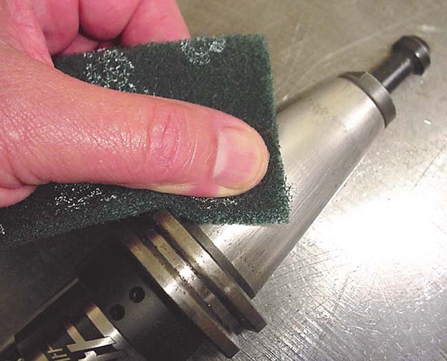
Use a kitchen scouring pad to remove rust from a toolholder. Image courtesy of J. Harvey.
- Producing parts via 3D printing can save time. Often, designers are not completely sure of themselves when designing prototype parts. They’ll order one part from a machine shop and, if it works, they’ll order more. This method is inefficient from a shop’s perspective because shop personnel must find a suitable material, come up with the proper cutters, correctly program the job, effectively set up the machine and run a good part. If the part doesn’t work, the process starts over. I’ve found that 3D printers are easy to use. Besides the printer, all that’s needed is a CAD model and the powder material. Once you have a CAD model, all you have to do is print the part, possibly tap some holes and hand it to the designer. If all is well, the designer will order machined parts only once.
- Burrs are a fact of life in machining. Any cutting tool will throw a burr; sharp tools less so. Burrs must be removed from machined parts by hook or crook (often by a file). If you rerun the initial facing tool over the part after you have machined features such as holes and the perimeter of the part, you reduce the effort it takes to remove burrs simply because many of them get cut off during this final pass.
- Cut hard materials with carbide cutting tools, don’t apply coolant (just air, if available), run tools at slow spindle speeds and take DOCs from 0.002" to 0.003". After parts get hardened via heat treating, they often need rework for various reasons.
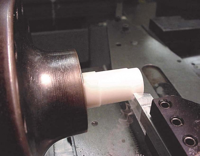
An aluminum tool machines a Delrin part. Image courtesy of J. Harvey.
- Cutting tools must be harder than the material they machine. This sound obvious within the realm of machining. To experiment, I took this concept a step further. I ground a piece of 7075-T6 aluminum into the shape of a lathe tool and proceeded to cut a Delrin part. Delrin is a rigid plastic, which is relatively stable and easy to machine. The aluminum tool held up well and imparted a fine surface finish.
- Use negative-rake endmills to push flimsy parts down onto your parallels and holding fixtures. The cutting force of negative-rake endmills tends to push the material being cut toward the bottom of the endmill. You can use this force to your advantage when machining parts that are not held too securely. The force tends to push parts against parallels instead of pulling them off, as would be the case when applying positive-rake endmills. The rake angle of a cutter is the angle that chips slide over.
- In a pinch, use a CNC machine to broach blind keyways, which are often cut with an EDM. The programming and setup can be tricky on a CNC machine because it’s probably not something you often do. The spindle must be lined up and locked using an M code. First, rough out as much of the keyway as practical with an endmill. Then, find or make a sturdy broaching tool and program the tool to take light cuts (0.001") as it enters the roughed-out slot. Use cutting oil. I’ve found this method is faster than EDMing.
[Editor’s note: This column is the final installment from “CNC Trade Secrets.”]
Related Glossary Terms
- broach
broach
Tapered tool, with a series of teeth of increasing length, that is pushed or pulled into a workpiece, successively removing small amounts of metal to enlarge a hole, slot or other opening to final size.
- broaching
broaching
Operation in which a cutter progressively enlarges a slot or hole or shapes a workpiece exterior. Low teeth start the cut, intermediate teeth remove the majority of the material and high teeth finish the task. Broaching can be a one-step operation, as opposed to milling and slotting, which require repeated passes. Typically, however, broaching also involves multiple passes.
- computer numerical control ( CNC)
computer numerical control ( CNC)
Microprocessor-based controller dedicated to a machine tool that permits the creation or modification of parts. Programmed numerical control activates the machine’s servos and spindle drives and controls the various machining operations. See DNC, direct numerical control; NC, numerical control.
- computer-aided design ( CAD)
computer-aided design ( CAD)
Product-design functions performed with the help of computers and special software.
- coolant
coolant
Fluid that reduces temperature buildup at the tool/workpiece interface during machining. Normally takes the form of a liquid such as soluble or chemical mixtures (semisynthetic, synthetic) but can be pressurized air or other gas. Because of water’s ability to absorb great quantities of heat, it is widely used as a coolant and vehicle for various cutting compounds, with the water-to-compound ratio varying with the machining task. See cutting fluid; semisynthetic cutting fluid; soluble-oil cutting fluid; synthetic cutting fluid.
- cutting force
cutting force
Engagement of a tool’s cutting edge with a workpiece generates a cutting force. Such a cutting force combines tangential, feed and radial forces, which can be measured by a dynamometer. Of the three cutting force components, tangential force is the greatest. Tangential force generates torque and accounts for more than 95 percent of the machining power. See dynamometer.
- electrical-discharge machining ( EDM)
electrical-discharge machining ( EDM)
Process that vaporizes conductive materials by controlled application of pulsed electrical current that flows between a workpiece and electrode (tool) in a dielectric fluid. Permits machining shapes to tight accuracies without the internal stresses conventional machining often generates. Useful in diemaking.
- endmill
endmill
Milling cutter held by its shank that cuts on its periphery and, if so configured, on its free end. Takes a variety of shapes (single- and double-end, roughing, ballnose and cup-end) and sizes (stub, medium, long and extra-long). Also comes with differing numbers of flutes.
- lapping compound( powder)
lapping compound( powder)
Light, abrasive material used for finishing a surface.
- lathe
lathe
Turning machine capable of sawing, milling, grinding, gear-cutting, drilling, reaming, boring, threading, facing, chamfering, grooving, knurling, spinning, parting, necking, taper-cutting, and cam- and eccentric-cutting, as well as step- and straight-turning. Comes in a variety of forms, ranging from manual to semiautomatic to fully automatic, with major types being engine lathes, turning and contouring lathes, turret lathes and numerical-control lathes. The engine lathe consists of a headstock and spindle, tailstock, bed, carriage (complete with apron) and cross slides. Features include gear- (speed) and feed-selector levers, toolpost, compound rest, lead screw and reversing lead screw, threading dial and rapid-traverse lever. Special lathe types include through-the-spindle, camshaft and crankshaft, brake drum and rotor, spinning and gun-barrel machines. Toolroom and bench lathes are used for precision work; the former for tool-and-die work and similar tasks, the latter for small workpieces (instruments, watches), normally without a power feed. Models are typically designated according to their “swing,” or the largest-diameter workpiece that can be rotated; bed length, or the distance between centers; and horsepower generated. See turning machine.
- lathe bit ( lathe tool)
lathe bit ( lathe tool)
Cutting tool for lathes and other turning machines. Normally a single-point cutting tool, square in cross section and ground to a shape suitable for the material and task. Intended for simple metal removal, threading, slotting or other internal or external cutting jobs. Clearance to prevent rubbing is provided by grinding back rake, side rake, end relief and side relief, as well as side- and end-cutting edges.
- rake
rake
Angle of inclination between the face of the cutting tool and the workpiece. If the face of the tool lies in a plane through the axis of the workpiece, the tool is said to have a neutral, or zero, rake. If the inclination of the tool face makes the cutting edge more acute than when the rake angle is zero, the rake is positive. If the inclination of the tool face makes the cutting edge less acute or more blunt than when the rake angle is zero, the rake is negative.
- tap
tap
Cylindrical tool that cuts internal threads and has flutes to remove chips and carry tapping fluid to the point of cut. Normally used on a drill press or tapping machine but also may be operated manually. See tapping.
- toolholder
toolholder
Secures a cutting tool during a machining operation. Basic types include block, cartridge, chuck, collet, fixed, modular, quick-change and rotating.