Smoother Roughing
Smoother Roughing
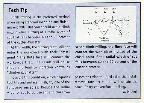
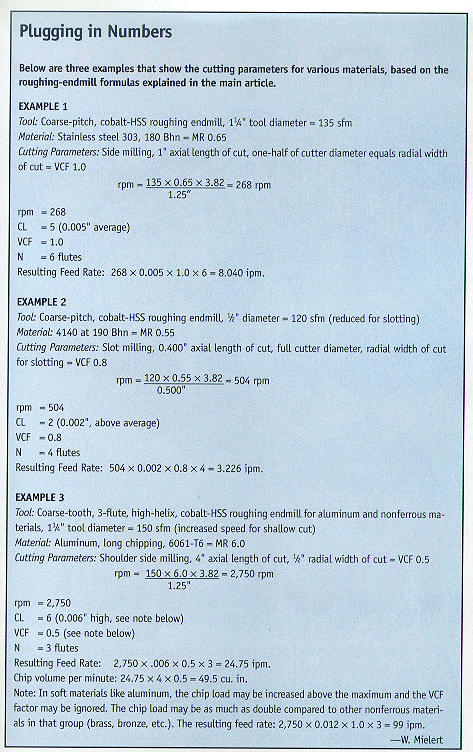
The author discusses the disadvantages of using a finishing endmill for roughing applications. He also presents a quick, systematic, step-by-step series of calculations that allows machinists to optimize metalcutting when applying coarse-pitch, cobalt-HSS roughing endmills.
Many people use cobalt-HSS finishing endmills for roughing, semifinishing and finishing operations. The advantage is that one tool performs the work of three. Among the disadvantages are that roughing can't be done as quickly with a finishing endmill and the finisher removes less material per unit of spindle horsepower.
For example, a 3/4"-dia. rougher will remove about 100 percent more material than a 3/4"-dia. finisher run on the same spindle. And the material-removal rate of a 2"-dia. rougher is more than double the mrr of a 2" finisher.
Additionally, compared to finishers, roughing endmills can make larger axial and radial cuts at heavier feed rates while experiencing lower side pressure. The reason is because of the unique sinusoidal, or "knuckle," tooth form of the rougher's radial cutting edge.
The knuckles form chipbreakers along each cutting edge. Their sinusoidal shape means the tool has no sharp corners that can cause premature wear and edge breakdown. The knuckles are staggered from one flute to the next so that the knuckles on following flutes cut to the right and ahead of preceding flutes. This feature causes the rougher to generate relatively thick, comma-shaped chips on the lower side of a knuckle - the side that faces away from the tool shank and spindle.
Most of the cutting pressure is directed against the underside of the knuckle-up toward the spindle - while the tool's helical flutes direct the remaining pressure downward, away from the spindle. These pressures effectively cancel each other out and greatly reduce side pressure and the resulting deflection.
xxMany machine operators run cobalt-HSS roughing endmills at cutting parameters similar to the ones they use for finishers. They mostly rely on "feel" or by what looks or sounds right. The results are often disappointing. Tool life is poor, the tools burn up or break and the milling results are unacceptable.
These negative results can be largely eliminated when applying standard, coarse-pitch, cobalt-HSS roughing endmills by performing the quick, systematic, step-by-step series of calculations that follow.
Finishing endmills remove less material per unit of horsepower than roughing endmills. A rougher can double, or even triple, the mrr of a finisher.
 Determine the machinability of the material to be machined, based on hardness (Rockwell C or Brinell), material type, toughness and alloy content. A good source is the universal "Machinability Rating" (MR), originally developed by Metcut Research Associates Inc. for the Defense Logistics Agency. Table A gives the MRs for a number of popular materials. Plug the selected rating into the formula in Step 2.
Comments about Step 1: The MR will be affected by any changes in material hardness caused by heat treatment or other processes. Generally, the harder the material, the lower the MR will be. Therefore, it is important to know the true hardness of the material to be roughed.
 Calculate rpm for the tool diameter of the roughing mill using the following formula:
Comments about Step 2: The 135-sfm value is the basic cutting speed chosen for cobalt-HSS tools at a 100 percent MR. When multiplied by the MR value of the material to be machined, the cutting speed is adjusted to the proper value for that material. The constant factor for transposing sfm to rpm is 3.82. Divided by the tool diameter to be used, the proper rpm value for the tool is established.
Be aware that tool coatings will increase the cutting-speed (rpm) value. If you purchase a coated rougher, check with your tool supplier for a percentage increase and add this value to 135.
A second factor that will change the basic surface-footage value is the "time in cut" the cutting edge travels per revolution. When the time is low - say, a shallow cut where less than 10 percent of the tool's diameter equals the radial DOC - the sfm value may be increased to 150 sfm at a 100 percent MR. In a wide cut, as is found in slotting, the value should be reduced to 120 sfm.
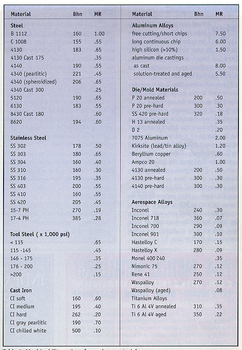
Table A: Machinability ratings for various materials.
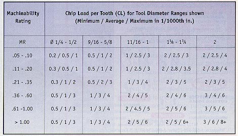
Table B: Chip load per tooth
 Feed per tooth (chip load) selection.
These values are presented in a simple tabular form to ease selection (Table B). They are based on MR percentages, type of roughing tool - coarse or fine pitch - and tool diameter.
Comments about Step 3: It is not recommended to run below the minimum chip load or above the maximum CL. If the type of pitch (coarse, medium, fine) is not known, here is a useful rule of thumb: Measure the knuckle depth of the rougher to be used (major diameter of tool minus minor diameter divided by 2, or the depth of the knuckle, measured from the top of the knuckle to its bottom). Use a percentage of this dimension as the feed per revolution. For example, use 50 percent of the knuckle depth as feed per revolution on a material with an MR of 0.60 to achieve a medium-heavy feed per tooth. Reduce the value for harder materials or wide cuts, and increase it slightly for softer materials or shallow cuts.
 Calculate the Volume Cut Factor.
VCF is based on the theory that a tool with a specific geometry, length, diameter, number of flutes, etc., can remove a specific volume of a particular material without breaking. Let's say that a 1"-dia. tool is successfully cutting at 2 times its diameter (axial length of cut) and 0.5 times its diameter (radial width of cut). The feed is 10 ipm. The cut volume calculates out to 10 cu. in. per minute (2 5 0.5 5 10 = 10). To change the cutter-engagement values, we could change a couple of the parameters and still come up with the same VCF.
For example, we could alter the radial width of cut by one-half (0.25 5 tool diameter) and double the feed rate (20 ipm). The resulting VCF would remain the same (2 5 0.25 5 20 = 10). As long as you stay near the recommended chip load, the parameters can be varied and combined so that the operation can be performed in the quickest, most efficient way possible without breaking the tool.
The material volume and VCF are established on the basis of the type of cut (peripheral side milling, shoulder side milling, slot milling) and on the axial length of cut in relation to the tool diameter. The resulting multiplier is plugged into the formula in Step 5 to modify the feed-rate value. Use Table C to establish the VCF.
 Calculate the feed rate. The feed formula includes the values calculated in the previous steps (rpm, CL, VCF) multiplied by the number of flutes (N) the roughing mill has. Enter the values established in Steps 2, 3 and 4 into the following formula:
Feed rate (ipm) = rpm 5 CL 5 VCF 5 N
Comments about Step 5: It's recommended that you choose feed and speed values somewhat conservatively when starting out to make sure that your fixturing is adequate and that your machine has ample power. Increase the cutting speed and feed rate in 5 percent increments to find the optimum, aggressive parameters acceptable in terms of machining results vs. tool life.
Note: If you arrived at a low VCF and you also have chosen a low CL, the resulting feed per tooth may be below the recommended minimum CL. Adjust your rpm downward to reach a feed per tooth at or above the recommended minimum.
It takes only a short time to perform these calculations - one or two minutes. But you will find that it's time well spent, as your machining time decreases, tool life increases and you start machining more accurate parts.
About the Author
Wolfried Mielert is co-owner and CEO of IZAR Tool LLC, Bloomfield, Conn.


