Strictly Boring
Strictly Boring
When machinists plan a boring operation, they must rely on general turning data. Typically, this data is developed from OD turning operations, not boring operations. This article provides cutting data and recommendations specifically for boring that take into account such unique problems as boring bar deflection and chips trapped inside the bore.
Boring-tool users would do well to pass up general turning recommendations in favor of technical data devoted solely to this one operation.
Developers of technical data for turning seem to have all but forgotten about boring. Typically, when users want advice on carbide grades, chipbreakers, feed rates, or other cutting conditions for boring, they settle for the general turning data they find in machining handbooks and the technical sections of their suppliers' catalogs. Almost all of the general turning information found in the reference literature, however, is generated from OD turning studies. Researchers prefer OD turning because it's the simplest turning operation to perform, and the process can be easily observed. Once the researchers' findings are published, the information becomes gospel for all turning operations.
This general information might be acceptable if it truly applied to a broad range of turning operations. But, as frustrated users have discovered, boring with cutting conditions set according to this gospel can lead to such problems as poor surface finish, short tool life, inconsistently sized holes, broken inserts, and broken boring bars. To avoid these pitfalls, operators must understand how boring differs from OD turning and know which parts of the published data must be modified to fit their applications.
Poor Surface Finish
Most published data states that a part's surface finish is directly related to the user's choice of feed rate per revolution and nose radius size. This is certainly true as far as it goes. The user should be able to obtain whatever surface finish he desires on the OD of a turned part simply by concentrating on these two cutting conditions.
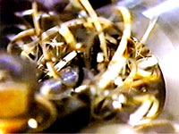
Figure 1: Stringy chips that don't exit the bore freely can damage the surface of the bore wall.
However, if the user is boring the part, he must consider other factors. For example, the size and shape of the chip can have a significant impact on surface finish. Unlike OD turning, in which chips can fall away from the part, the chips that boring creates can become trapped within the bore. As the boring operation proceeds, the trapped chips lodge between the boring bar and the part's ID. The chips' contact with the part damages the surface and leads to poor surface finish. This is most likely to happen with large chips that can't escape from the bore opening or stringy chips that wrap around the boring bar (Figure 1). Small broken chips or chips that form long straight strings exit more freely.
Chip-control strategies in ID turning are similar to those in OD work. In OD turning, it is a good idea to carry out these strategies because they make the operation safer and chip disposal more convenient. In boring, these measures are essential to prevent chips from jeopardizing the success of the operation. Generally speaking, faster speeds and heavier feed rates will break chips into smaller pieces. The user may not be able to control chips using these measures, however. The machine may be incapable of faster speeds or heavier feeds. In such cases, the user should mount the inserts in the smallest boring bar available, provided the bar's overhang-to-diameter ratio won't exceed the ratio recommended for the bar material. This gives the chips more room within the bore to move without scraping against the part's ID surface.
If chips are curling around the boring bar and creating problems, a slower cutting speed might help by creating a long straight chip. A chipbreaker geometry on the cutting insert can produce smaller chips as well. But boring-tool users have fewer geometries to choose from than they would find for OD turning. Boring inserts must be small to fit inside the hole; the smaller the bore, the smaller the insert. This leaves less room on the insert surface than on an OD turning insert for complicated geometries.
Above the Centerline
Although it is rarely mentioned in the technical literature, the surface finish of a bore also can be affected by the deflection of the boring bar. When a boring bar deflects, a cutter mounted in the bar and positioned at the centerline of the bore is forced downward into the bore's lower curvature. This action forces the cutter to dig into the part, and under the heavier cutting forces it begins to chatter or it breaks, damaging the part surface in the process (Figure 2).
Figure 2: Deflection of an insert positioned on the centerline causes the tool to dig into the bore wall and produces a bore diameter that is larger than specified (A). Deflection of an insert positioned above the centerline moves the tool away from the bore wall and produces a bore diameter that is smaller than specified (B).
Tool deflection also can cause a roughing cutter to remove too much material, leaving too little stock for the finish pass to produce a good surface finish. This can occur even if the part program is originally written to leave enough material. Variations in the work material or a loss of edge on the tool can increase tool pressure, causing the roughing bar to cut a larger hole than it is programmed to cut.
Deflection does not have such a severe effect on an OD turning operation. An OD turning toolholder's larger size and shorter overhang make it less prone to deflection, and any deflection that does occur will push the cutter down and away from the part. In boring, it is impossible to use massive toolholders that won't deflect. Simply put, if the boring bar is too large, it won't fit into the bore.
Even though a user can't switch to a larger bar, there are some measures he can take to reduce the amount of bar deflection. Table 1 lists the factors that determine deflection, along with suggestions for reducing each factor's influence. Table 1 also offers a formula for calculating deflection. As this formula shows, the factor that has the greatest effect is the length of the overhang. Small increases in overhang, which is cubed in the formula, lead to exponentially larger amounts of deflection. For example, a 0.250"-dia. carbide boring bar with a 1" overhang (giving it a overhang-to-diameter ratio of 4-to-1) will deflect 0.0005" in steel at a 0.0120" depth of cut (DOC) and a 0.0050" feed rate. Increase the overhang by 25% to 1.25", and the deflection increases by 100% to 0.0010". The elasticity/" data-glossary-id="141729" data-glossary-teaser="Measure of rigidity or stiffness of a metal, defined as a ratio of stress, below the proportional limit, to the corresponding strain. Also known as Young’s modulus." title="Measure of rigidity or stiffness of a metal, defined as a ratio of stress, below the proportional limit, to the corresponding strain. Also known as Young’s modulus." aria-label="Glossary: modulus of elasticity">modulus of elasticity is also a significant factor because of the difference in elasticity between steel and carbide. Had the boring bar in the previous example been steel, deflection would have been close to 50% greater. (Table 2 lists the degrees of boring-bar deflection that occurred in tests using different boring-bar materials and sizes under typical boring conditions.)
The measures listed in Table 1 may not eliminate deflection altogether. To compensate for any deflection that may remain, the cutting tip needs to be positioned above the centerline. The distance above the centerline depends on the amount the boring bar will deflect in the cut as predicted by the formula in Table 1. The tip should not be positioned too high, however. This reduces the area for the chip to form above the insert. As the cutting action compresses the chip into this smaller space, it increases the cutting forces and may cause the chip to become welded to the cutting edge.
Some companies manufacture boring bars with the insert tip 0.010" above center on the assumption that the maximum recommended cutting conditions will not deflect the boring bar more than this amount. In some applications, however, this may be too much offset to produce the best surface finish, especially when cutting with inserts that are tipped with polycrystalline diamond or cubic boron nitride. Using the formula for deflection or the guidelines listed in Table 2, the user can determine the actual amount a boring bar will deflect in a given application. If this deflection will be less than 0.010", the boring bar can be rotated to bring the cutting tip closer to the centerline.
Short Tool Life
When referring to technical literature, boring-tool users should approach the recommendations for optimizing tool life with as much caution as they approach recommendations for improving surface finish. Like reference sections on surface finish, tool-life guidelines were drafted using data from OD turning studies and may not be entirely applicable to boring.
For all applications, tool life is expressed as the accumulated time in the cut or number of parts produced from the time a new cutting tip is indexed into position to the time it can no longer produce an acceptable part. To calculate an economically acceptable tool life, the user must take into account the average cost of a standard insert, the time it takes to index the cutting tool, and the machine burden rate. Given these factors, most users are satisfied to get 15 to 20 minutes of cutting time out of their carbide inserts. In boring, when tool life falls below this level, the user should look for problems at the cutting edge first. Problems such as insert breakage, chipping, deformation, and flank wear are more likely to cause a boring tool to fail than machine malfunctions or variations in the workpiece. The course the user takes to increase tool life will depend on the type of problem he is experiencing.
Breakage. The cutting tool may fail prematurely because the insert is breaking at the corner. A common cause of breakage is cutting force that exceeds the capacity of the boring bar's pocket support. Once again, it is the bar's smaller size that makes it more susceptible to problems than an OD turning toolholder. If a boring bar had as much support under the tool as a turning toolholder, it might be too large to fit inside the bore.
Lacking the support of a turning toolholder, a boring tool cannot cut metal as aggressively as an OD turning tool. If the maximum DOC and feed rate that are possible with a turning tool are applied to a boring bar, the pocket will most likely deflect or break even before the shaft of the boring bar itself does. This pocket deflection will let the insert drop below the centerline. If this causes the tool to dig into the part deep enough, the insert may fracture. Often, as the insert breaks apart, the pieces will damage the pocket of the boring bar. A damaged pocket offers even less support to the insert. A 10% loss of pocket support could result in a 20% reduction in the amount of cutting force that the insert will withstand.
Chip packing is another common cause of insert fracture, but this problem is not as easy to detect. It occurs most often when boring blind holes or when boring the larger diameter of a multidiameter through hole. In the case of a blind hole, if the boring operation generates chips faster than they can exit the bore, the chips will become tightly packed in the bottom of the hole, where they will obstruct the cutting action of the insert and put increased force on the tool until it fractures. One possible cure for this syndrome is to bore from the bottom out by moving the tool toward the center of the hole, inserting it into the hole, feeding the tool over to the diameter, and then boring the hole to size while drawing the tool out of the hole. This method of boring not only creates space for the chips, but also puts the bar in tension, making it slightly stiffer than it is when it is compressed during a conventional boring operation.
Chip packing can be avoided even during conventional top-to-bottom boring as long as the user allows enough space for chips to escape between the boring bar and the bore. Experienced users can tell if there will be a problem simply by observing the space in the bore and the size of the chips being produced. These users also know that when they are boring holes that are close to the boring bar's published minimum bore size, they must reduce the DOC and feed rate to allow chips to exit the hole.
Insert chipping. Inserts don't have to break to cause problems. Even a small chip in a carbide insert can produce accelerated wear on the tool and a poor surface finish on the part. Typically, chipping occurs when chips from the workpiece, flying around at high velocity inside the bore, break off tiny pieces of the cutting edge. A break in the edge becomes a stress point, and the tiny flaw soon propagates into a larger chip in the insert. Small pieces also can be broken off of the insert when chips from the workpiece jam between the cutting edge and the part. The insert becomes chipped as the tool proceeds to recut the workpiece chips in its path.
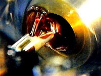
Figure 3: A through-coolant boring bar ensures the delivery of coolant at the cutting tip, where it's needed most.
The user can prevent insert chipping by keeping workpiece chips flushed out of the bore with a flow of coolant. On bores that are more than twice their diameter in depth, a through-coolant boring bar should be used (Figure 3). Delivering coolant close to the cutting edge with a through-coolant tool not only will flush chips out more effectively than using a separate nozzle to direct coolant at the insert, but also will keep the cutting tip cooler and improve the part's surface finish. In situations where coolant cannot be directed at the cutting edge, an air line attached to the boring bar could be used to remove chips from the bore and cool the insert.
Through-coolant boring bars are available for bores as small as 0.180" in diameter. The smallest bars have a 0.040"-dia. hole for the coolant to pass through. For boring, a water-based, through-coolant delivery system needs a pump rated at a minimum of 20 psi and 20 gpm. If a coolant flow at this pressure and volume is not sufficient to flush chips out of the bore, the user might consider installing a high-pressure pump. Aftermarket pumps are available with ratings of 1,500 psi or higher. Manufacturers of these pumps claim a high-pressure delivery system will increase tool life, improve surface finishes, and allow steel to be bored with overhang-to-diameter ratios up to 15-to-1. Preliminary tests seem to confirm these claims.
Regardless of the type of pump used, an effective coolant filter is a necessity with through-coolant boring bars. Large chips can plug the coolant hole in the boring bar, if they are allowed to pass through the system.
Deformation. Heat can shorten an insert's life by causing the cutting tip to mushroom out, much as the corner of a piece of soft steel might do if it were hit with a hammer. This happens when the tip becomes hot enough to soften the tool's binder. The binder for most carbide inserts is cobalt, which softens at 950° to 1,000° F.
Surface speed has the greatest effect on the temperature of the cutting tip. Higher speeds generate more heat. Remaining within the speed ranges recommended in the technical literature won't ensure a successful boring operation, however. Like other guidelines in the literature, these speed recommendations are based on data gathered from studies of OD turning, which is not as susceptible to heat damage. In OD turning, the heat that is transferred into the chip is carried away when the chip falls from the workpiece. In boring, the chip remains, at least temporarily, in the bore, where it has a chance to transfer some of its heat back into the insert or the part.
A user can correct insert deformation by reducing the surface speed. However, this remedy may lower productivity more than the increased insert wear did. Installing a through-coolant boring bar and coolant-delivery system will probably prove to be a more productive way to control temperatures at the cutting tip.
Flank wear. Flank wear is the only predictable mode of insert failure. As long as the work material remains consistent and the carbide grade remains the same, the user can calculate the rate at which the wear land will develop. Knowing this, the user can develop a schedule for indexing the insert before the wear leads to catastrophic failure. The amount of flank wear that is tolerable varies from operation to operation. Some technical information recommends indexing the insert at 0.030" flank wear, but this would be a catastrophic amount of wear for a small boring insert that may be only 0.040" thick. Inserts for bores less than 0.625" in diameter should be indexed after flank wear of 0.003" to 0.010".
Varying Hole Size
Inconsistent hole size is another boring problem that is not well covered in technical literature based on OD turning studies. Users seeking a solution to the problem will have to rely on whatever information they can gather from the parts.
If they find that the bore diameter varies from part to part, but each individual bore's diameter is consistent along its entire length, their machine may be the source of the problem. A machine with worn ballscrews will position the cutting tip in a different place each time it moves to a new part. On CNC machines, users can compensate for this wear with offsets in the part program.
Figure 4: Operators can reduce indexing error by rotating the boring bar a quarter turn in the turret.
On a flatbed turret lathe, the accuracy of the bore typically depends on how precisely the turret can position the boring bar when it indexes to a new tool. A 0.001" error in the positioning can result in a bore diameter that is 0.002" too large or small. Errors introduced by the turret can be significantly reduced by rotating the bar a quarter turn so that the top of the insert is parallel rather than perpendicular to the rotational axis of the turret (Figure 4). With the insert in this position, a 0.001" indexing error changes the diameter of the hole only 0.000002".
A user who finds that each bore is tapered should suspect boring-bar deflection. If a bore gets larger from top to bottom, it indicates that tool pressure is deflecting the bar and forcing the cutting tip below center. As the tool digs into the wall of the hole, it puts more pressure on the bar, causing it to deflect even more. The operator can't compensate for this deflection in the part program, because it is impossible to predict how much additional pressure and deflection will occur once the insert starts to dig in.
The problem can be avoided, however, by using a high-quality boring bar that positions the cutting tip above center. With the cutting tip in this position, deflection results in lower cutting pressure, because the cutting tip moves away from the curvature of the wall as it dips down. The result is a hole that gets smaller from top to bottom. This type of deflection is more predictable, because the insert does not dig in and produce additional cutting pressures. Because of this predictability, it is possible for the user to program compensation into the cutting path. Even if the inward taper can't be compensated for completely, parts don't have to be scrapped. The operator can rework them to straighten the bore.
Sometimes boring-bar deflection is caused by an overhang-to-diameter ratio that is too large for the bar material. A rule of thumb in the metalcutting industry states that overhang ratios for steel bars should be no larger than
5-to-1. Carbide bars can be used with overhangs up to 10-to-1. Even if the ratio is within the boring-bar material's range, deflection may occur if the cutting conditions are too severe. To be safe, the operator should decrease the DOC and feed rate as the overhang ratio increases.
Breakage
Any of the problems already discussed can lead to catastrophic insert or boring-bar failure. If these problems are corrected and the inserts or bars continue to break, it may indicate a problem with the machine setup. Parts, especially thin-walled parts, must be held securely to prevent insert or bar breakage.
Breakage also can occur if the boring bar is not held rigidly. Bars held with collets are the least likely to move. Because of this, some bars are manufactured without a flat so they can be used with a collet. If a collet cannot be used, the operator should mount the bar in a block with a hole size as close as possible to the boring bar's shank diameter. The operator might also choose a boring bar with a step shank, which offers more rigidity than a boring bar in an aftermarket sleeve. The operator should not stack several sleeves together to mount a small-diameter boring bar in a large hole. Even though it may cost more to use a special sleeve, block, or boring bar, the added expense will pay off in a higher quality bore.
Acceptable variations between parts can cause intermittent insert breakage if the part program does not allow for these deviations. The part programmer must make sure that the cutting tip will always be some distance from the part when the machine changes from a rapid to a boring feed rate despite any part variations that might occur. The programmer also should expect slight variations in the way parts are chucked. Because of these variations, some parts may be higher in the fixture or located further to one side or the other than other parts. The program must move the boring bar far enough from the part to prevent crashes during indexing or rapid feed changes wherever the part might be located in the fixture.
Finally, some breakage may be the result of operations performed prior to boring. For instance, the process used to produce the hole may harden the hole wall if the tool does not cut freely and the part is made of a workhardening material. If inserts continue to break after other causes of tool breakage have been eliminated, the operator should suspect workhardening as the reason. To bore material that has been hardened by another cutting process, the operator will have to reduce surface speed and, possibly, select a different grade of insert. If a drill is used to produce the hole, the operator should make sure it is securely held. A drill that slips back into its holder as cutting pressures increase will produce a hole that is too shallow. When the bore reaches the bottom of the hole, the shock will break the boring bar and may even damage the machine.
With all the problems that can occur, boring holes is almost never boring. The process doesn't have to be a user's worst nightmare, however. Operators can avoid most problems by using high-quality boring bars, checking the setup, and monitoring the operation by examining the chips being produced. If they also rely on technical information based on boring-operation data, they are almost sure to produce trouble-free, high-quality bored holes.
About the Author
Harvey Patterson is plant manager and manager of R&D for Circle Machine Co., Monrovia, CA.


