Turning Implants
Turning Implants
As the orthopedic implant market grows, manufacturers and shops search for new turning center technology to ensure a competitive edge.
As the orthopedic implant market grows, manufacturers and shops search for new turning center technology to ensure a competitive edge.
America's aging baby boomers, intent on maintaining an active lifestyle, are driving a buoyant orthopedic implant market that's expected to rise 9.8 percent per year, to $23 billion by 2012, according to the Freedonia Group, a Cleveland-based market research firm.
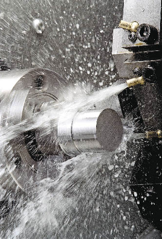
The market's four leading segments—knee, spine, shoulder and hip implants—all are machined on turning centers. And as demand for the orthopedic devices grows, so does competition among turning center builders and job shops.
Courtesy of Haas Automation
The Haas Automation SL-10 turning center features a 15-hp (peak) vector drive spindle that provides speeds up to 6,000 rpm for high surface feed rates.
Industry representatives contacted for this story stressed the importance of maintaining an edge. Many are trying to do so with new technology to improve and speed production. Some shops also highlight the fact that their machining methodology—and thereby the ensuing products—adhere to high standards.
At Jade Precision Medical Components LLC, Southampton, Pa., maintaining ISO certification has been a prime factor in staying competitive, said Robert Bradby, the company's production manager.
"It's a huge sales tool for us. [Implant manufacturing] is all about traceability, processes and procedures. That's what most customers want to see," he said.
Bradby estimated that Jade Precision, which focuses primarily on spinal implants, produces about 4,000 to 6,000 components per week. "Ninety percent of our product is Ti6Al4V, which is an implantable-grade titanium," he said. "The other 10 percent is 316-L stainless steel." Bradby explained that companies order implants made of stainless for people who, in rare cases, are allergic to titanium, or if the surgeon plans on removing the implant in the near future. Stainless steel is the preferred option in the latter case because "tissue adheres to and grows around titanium much better than it does steel," said Bradby.
From Bradby's vantage point, the thrust of advances in turning technology has been to boost production speed. "Most of it is through noncutting movement, getting from one tool to another quicker so you can decrease cycle time and increase throughput," said Bradby. "It doesn't necessarily make my job easier, but it does get things out the door quicker, which is a good thing."
While Jade Precision previously had only Star turning machines to produce spinal implant components, it recently acquired five 5-axis milling machines to handle some of the work that couldn't be accommodated on the Swiss-style automatics. "We will be able to go after more of the market than when we only had Swiss machines," he said. "In some cases, you can machine with up to three axes, but in the end the [Swiss] machines are lathes and not mills, which is why we now have a 5-axis milling department."
Multitasking Matters
In addition to providing turning centers with three or more axes, machine builders offer a range of technologies for turning implants. For example, one development at Mori Seiki USA, Rolling Meadows, Ill., is the combination of milling, turning and grinding its NT and MT series of machines.
"They're mill/turn/grind centers," said Greg Hyatt, vice president of engineering and chief technical officer of the company's Machine Technology Laboratory. "They can improve quality and productivity. For example, sometimes the sequence of operations doesn't allow you to do all the turning in one operation and all the milling in another."
To prevent workpiece deformation, he continued, machinists may need to do all of the roughing on turning and milling machines before completing the finishing on either. "That would involve more setups and poorer response time, which is critical for the specialized components that may be patient-specific," he said. "So the more specialized the component and the more responsive the manufacturing needs to be, the more valuable these integrated machines are, which in some cases can finish [an implant] in a single operation."
Another development at Mori Seiki is the recently introduced Spinning Tool for lathes. "While the definition of a lathe tool is a static tool with a rotating workpiece, in this case the workpiece rotates like on a normal turning center but the tool also rotates," he said. "So when cutting difficult alloys, we don't have one spot on the tool constantly engaged with the work, creating one hot spot on the tool and forcing us to reduce productivity to keep the tool from overheating and failing prematurely."
Hyatt explained that by rotating the tool at high speed, no point on the tool is engaged with the workpiece for more than a millisecond. Consequently, abrasion and the heat around the tool circumference are equally distributed.
Adaptive Balancer
While multitask centers offer advantages, they can come at a cost. When one machine mills and turns, the balance often changes during milling operations, causing spindle vibration. To adjust for balance deviations and ensure stability during both milling and turning operations, Mori Seiki recently introduced its Adaptive Balancer.
The device senses any imbalance and compensates for it by applying an equal force and opposite vector in the workpiece. The Adaptive Balancer is attached to the chuck and rotates with the part. It uses two independent, counter-weighted rings in its interior to compensate as balance changes in the workpiece.
The device is especially useful for some orthopedic implants. As Hyatt explained, shops typically produce a family of parts with variations—in the case of hip implants, for example, there may be different stem lengths to accommodate patients of various height and weight.
"Therefore," he continued, "when you move from one part in the family to another part—a hip joint with a longer stem or whatever the variable is—the imbalance forces change and unless you rebalance the workholding for every part in the family, you can end up compromising the quality of the workpiece or the tool life. Because these are critical parts, customers typically reduce the speed of the chuck so the quality of the workpiece is not compromised. But then they end up compromising productivity and cost."
Job Shop Input
Feedback from shops accounted for one of the latest developments at Mazak Corp., Florence, Ky. Chuck Birkle, vice president of marketing for the company's Cybertec Div., said space-conscious customers often seek machines with smaller footprints. To that end, the company introduced its new generation Integrex i-l50 multitask machine.
The model takes up 58 sq. ft. of floor space, 6 ' fewer than Mazak's smallest Integrex machine. "We were able to design a large work envelope with a small footprint by building it without a second spindle," said Birkle. "Usually these machines have a second spindle to grab the part and perform backside operations. However, the second spindle itself takes up room. This machine has a workhandling unit that grabs the part once it's machined, lifts it and points it up at the milling spindle."
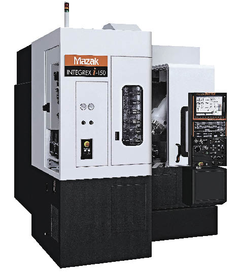
Courtesy of Mazak
Mazak's Integrex i-150 multitask machine takes up 58 sq. ft. of floor space and features a single, horizontal, main spindle and C-axis control.
It's thus capable of facemilling and drilling bars, providing the Y-axis machining ability of a machining center combined with the bar turning capacity of a turning center.
In addition to floor space benefits, the i-150 "also is flexible in terms of being able to machine the complex features we see in implants," said Birkle.
Smaller turning centers for machining orthopedic implants also is a focus for Haas Automation Inc., Oxnard, Calif., said Milton Ramirez, the company's turning product technical specialist. "Our most popular machines [for manufacturing implants] are our Office Lathes, OL1 and OL2," he said. The lathes can fit through a 36 "-wide doorway. In addition, Ramirez continued, they "have a provision for aftermarket air-driven or electrical live tooling attachments that run from 30,000 to 80,000 rpm."
Because of stainless steel's hardness, it's typically machined with light cuts, he said. Machinists, for example, might work with live tools on a lathe, such as endmills about 0.06 " in diameter, which take off about 0.01 " to 0.025 " during each cut with full tool engagement.
The company also has added new technology to the Office Lathe's control. "We call it IPS, or our intuitive programming system," said Ramirez, adding that the feature allows operators to directly program on the control. "Before you run the machine, you can verify the program, see a graphical representation [and, if needed] do programming on parts."
Hardinge's SP²
Modifying a turning center's control to provide optimal machining is among the latest developments at Hardinge Inc., Elmira, N.Y. The technique is called Super Precision Squared, or SP², explained Jeff Ervay, the company's director of global product management for turning and milling centers.

Courtesy of Haas Automation
Haas Automation's OL-1 incorporates the company's intuitive programming system, which allows operators to directly program the control.
"We have the ability to modify machining to enhance the true form of the part though data inputs in the control itself," he said. "SP² allows us to machine a part with what I'll call true part form, or true cylindicity. When the average company checks a part, they do it dimensionally with a pair of micrometers or verniers. They don't check the form of the actual part. But when you get into medical implants, you want that form to be as perfect as possible. SP² allows us to look at and modify the part's cylindicity as a whole: roundness, straightness, perpendicularity and taper combined."
Ervay provided the example of applying SP² to the machining of a super-precision part, "defined as 0.0002 " continuous machining," i.e., the ability to machine over time without human intervention.
"With these data point settings, we can actually move in 0.000002 " increments," he said. "For instance, we can take a part, blow it up 4,000× and see its imperfections. Then we can go in the control, modify those areas of imperfections and provide an improved part."
Ervay said SP² has yet to be used for machining orthopedic implants, though he anticipates it will. And in light of recent developments in implant manufacturing that day probably isn't too far off.
A dominant theme in the evolution of turning centers during the past several years has been increasing productivity. That trend will likely continue as the market expands and manufacturers—determined to stay in the game—remain competitive. CTE
About the Author: Daniel McCann is senior editor of Cutting Tool Engineering. He can be reached at [email protected] or (847) 714-0177.
Contributors
Haas Automation Inc.
(800) 331-6746
www.haascnc.com
Hardinge Inc.
(800) 843-8801
www.hardingeus.com
Jade Precision Medical Components LLC
(215) 947-3333
www.jadecorp.com
Mazak Corp.
(859) 342-1700
www.mazakusa.com
Mori Seiki USA
(847) 593-5400
www.moriseikius.com


