What’s Your Angle?
What’s Your Angle?
When facemilling with an indexable-insert tool, the axial and radial rake angles of the inserts can have a significant impact on performance. This article reviews the basics of rake angles and their effect on tool life, cutter effectiveness and metal-removal rates.
Indexable-insert facemills are among the most expensive tools you can put into a toolchanger. They also have some of the most complex geometries of any tools.
Tool diameter, insert selection, lead angle and pitch are all important considerations during facemilling. However, the angle at which the insert enters the workpiece doesn't always get the attention it should. By using a facemill with the proper axial and radial rake angles, you will extend tool life, increase the cutter's effectiveness and maximize the metal-removal rate.
Lay the Groundwork
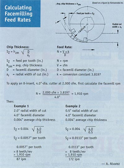
For a facemilling operation, the feed rate must be sufficiently high to allow each insert to engage the workpiece deep enough to begin cutting a good chip. If the feed rate is too low, the inserts will rub the workpiece, generating heat that could workharden the material and shorten tool life.
A rule of thumb is to specify a minimum feed rate of 0.004" per tooth. If you are using a facemill designed with a lead angle, the feed rate must be higher, depending on the angle used. If the radial width of the cut is less than half the cutter diameter, the minimum feed rate also must be higher than 0.004" per tooth. If the feed stays the same, the chips won't be thick enough, causing heat to build up.
The farther away the axis of the cutter is from the width of the cut, the thinner the chip is relative to the feed per tooth. Also, remember the general rule that a cutter should never have more than two-thirds of its diameter in the cut. If it does, the chip will be too small at the point the insert enters the material, and the insert will end up rubbing instead of cutting.
Strive to keep at least two inserts in the cut at all times in order to minimize chatter and excessive tool wear. A coarse-pitch facemill is recommended for machining soft materials that produce continuous chips and high chip loads. Fine-pitch facemills are more common for machining cast iron and high-temperature alloys and performing skim cuts with light chip loads. Using a facemill with a pitch that is too fine can cause chips to jam. If there is inadequate space in the pocket, chips will pack, plug and break the insert's cutting edge.
Successful facemilling begins with the initial contact between the insert and the workpiece material (Figure 1). A negative angle of entry is preferred because it ensures contact with the workpiece at the strongest area of the insert-away from the cutting edge. A positive angle of entry will cause the insert to make contact with the workpiece at the cutting edge, the insert's weakest point. This is where tool chipping usually occurs.
If you must use a positive angle-when the milling pass is less than half the cutter's diameter, for instance-then use an insert with a honed edge or a negative land clearance. This will maximize the strength of the cutting edge.
Climb, or down, milling is the preferred method for facemilling most materials. The cutter rotates in the same direction as the part being fed. This is analogous to an off-road vehicle's tire digging into the dirt when it climbs a hill. The cutting forces tend to pull the workpiece into the cutter, holding the insert in the cut. This method creates a thick initial chip that becomes thinner as it passes through the cutter rotation, but it doesn't rub the workpiece material.
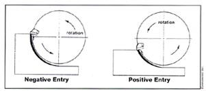
Figure 1: A negative entry angle ensures contact at the insert's larger cross section, reducing the risk of damage.
Angle Your Way to Better Cuts
 Axial and radial rake angles position the insert to enter the workpiece. They represent the insert's angular shift relative to a plane running through the cutter diameter.
If the insert is in the axial-negative position, the top of the insert is more forward relative to a line that is parallel to the facemill's axis of rotation and perpendicular to the workpiece. In this position, the cutting edge creates chips by scraping the workpiece, like a knife running across a cold stick of butter.
In the axial-positive position, the effect is the opposite. The top of the insert lags behind this line, creating chips the same way a shovel pushes snow.
The radial rake angle is the angular shift relative to a line that dissects the cutter diameter. This angle exhibits the same characteristics as the axial rake angle. In the radial-negative position, the top of the insert is more forward than the line, again creating chips like a butter knife. In the radial-positive position, the top of the insert lags behind the line, pushing the chips like a snow shovel.
Geometry Is as Geometry Does
There are three basic facemill geometries: double-negative, double-positive and positive-negative.
The double-negative facemill positions the inserts in negative axial and radial rake angles. It is used to rough-mill cast iron and hardened steels with machine tools that have good power and rigidity. The cutting forces are developed as the facemill is pushed into the workpiece.
A double-negative facemill is not recommended for machining thin, weak or unsupported workpieces, or for use with light-duty fixturing. A double-negative geometry can also workharden material and is prone to chip jamming in soft ductile materials.
While the double-negative design produces a poorer surface finish than the other geometries, it has a strong cutting edge that can withstand heavy chip loads and allows both sides of an insert to be used. These attributes make a double-negative facemill a good choice for roughing applications. However, the thick chips that develop result in high cutting forces that will require more machine horsepower relative to the metal-removal rate.
A double-positive facemill positions the inserts in positive axial and radial rake angles and cuts more efficiently with less machine horsepower, because it has a higher shear angle than a double-negative facemill. The high shear angle reduces the shock load at the tool's entry point and requires less cutting force.
A double-positive facemill is a good choice for less rigid setups or for machines with limited power. It also lends itself to the machining of fragile workpieces and materials that have a tendency to workharden. The high shear angle produces spiral chips that are directed out of the cutter, resulting in a better surface finish than the double-negative facemill.
The downside is that your tool costs will go up because you cannot use both sides of your inserts. Each insert in a double-positive facemill requires a ground clearance angle.
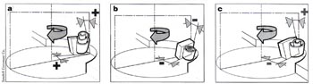
Figure 2: Shown are three geometric designs for facemilling: a) double-positive, b) double-negative and c) positive-negative.
The positive-negative facemill positions the insert with an axial-positive and a radial-negative rake angle, combining strong cutting edges with a high shear angle. The shearing action of the axial-positive rake angle also causes the chips to flow away from the cutter and the workpiece. This minimizes the recutting of chips and efficiently removes heat from the milled surface and inserts. Chips produced by a positive-negative facemill will generally not clog the cutter, a condition that can damage an insert's edge and mar the surface finish.
These features make the positive-negative facemill a good choice for heavy roughing cuts. In fact, when using a positive-negative facemill, a single pass may be enough to produce an acceptable surface finish.
The versatility of a positive-negative facemill will allow you to cut free-machining steels, as well as prehardened steels and cast iron, some of the tougher grades of aluminum and copper alloys. This type of facemill is also more forgiving when the setup is less rigid due to worn spindle bearings or a spindle with a long overhang.
Now that you have some basic understanding of the impact of insert angles on a facemilling operation, it is time to hit the shop floor and test what you've learned.
About the Author
Aaron Alvarez has more than 15 years of machining and manufacturing consulting experience. He is currently a senior manufacturing engineer at Raytheon Missile Systems in Tucson, Ariz.


