 Author Edmund Isakov, Ph.D.
Comparison between calculating cutting time when facing at a constant cutting speed vs. a constant rpm.

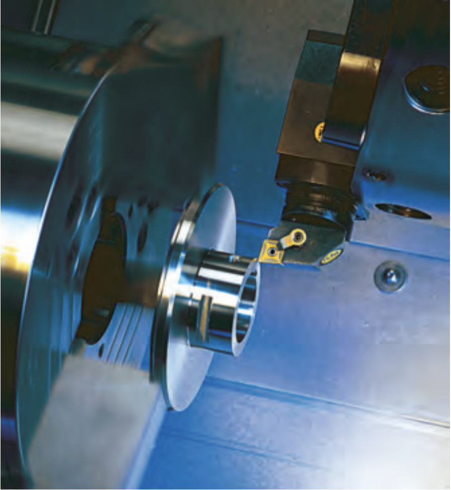
Facing being performed on a tubular workpiece. Image courtesy of Kennametal
Facing is a turning operation in which the workpiece is machined to its center. It involves moving the cutting tool perpendicular to the workpiece’s axis of rotation.
This operation can be performed at a constant surface speed (sfm, m/min.), which is recommended, or at a constant rotational speed (rpm), which is not recommended. Facing at a constant rpm decreases the cutting speed, because the diameter of the facing surface gradually decreases by the amount of a feed per revolution. The closer a cutting tool is to the center of a workpiece, the lower the cutting speed. It approaches zero at the center of a workpiece. A low cutting speed can cause built-up edge.
Cutting Time for Facing at Constant Cutting Speed
Formula: Cutting Time = (Initial Radius) / (Feed per Rev × RPM), where RPM = (12 × Cutting Speed) ÷ (π × Diameter)
Check out a more advanced Face Turning calculator here!
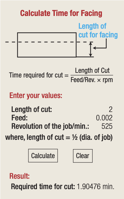
Therefore, end users have a dilemma: facing at a constant speed or a constant rpm. One way to calculate cutting time for facing is to use Web sites such as www.calculatoredge.com, which offers online calculators for engineers at no charge. Among the numerous categories, the lathe operations calculator provides a variety of calculations, including cutting time for facing. It calculates time for facing as a function of the constant rpm, workpiece diameter and feed per revolution. A representation of this calculator and an example of calculating time for facing at selected cutting parameters is shown in Figure 1.

Figure 1. The lathe operations calculator page for cutting time for facing from www.calculatoredge.com. Courtesy of Calculator Edge
The following are the author’s comments regarding this calculator:
- The formula for calculating time for facing contains a value “Feed/Rev.,” which is confusing because it can be interpreted as feed divided by revolution. These two words should be replaced by fpr (feed per revolution), which is the most commonly used value.
- Revolution of the job/minute is an awkward definition of the machine tool’s spindle speed, which is defined in rpm.
- Required time for cut is given in five decimal points, such as 1.90476 minutes in this article’s example. Such precise “astronomical” accuracy is unjustified. Two (maybe three) decimal places are more than enough for practical accuracy.
In many of today’s CNC machines, most operations, including facing, are programmed using constant cutting speed, which is specified in sfm in inch mode or m/min. in metric mode. At constant cutting speed, a CNC lathe automatically applies the correct rpm based on the following formulas for inch and metric systems:
rpm = 12 × sfm ÷ (π × cutting diameter in inches),
rpm = 1,000 × m/min. ÷ (π × cutting diameter in millimeters).
Constant Surface Speed Pros
Mike Lynch, president of CNC Concepts Inc., Cary, Ill., described four advantages of constant surface speed in his article “The Pros and Cons of Constant Surface Speed” (Modern Machine Shop, January 2009, pp. 62, 64).
- It simplifies programming. Speed can be directly specified in sfm or m/min., the units used by most cutting tool manufacturers for recommending speed. This eliminates the need to calculate rpm.
- It provides consistent workpiece finish. When used in conjunction with feed per revolution (feed rate mode), finish will be consistent regardless of the diameters machined.
- It optimizes tool life. Tools will always machine at the appropriate speed.
- It optimizes machining time. Cutting conditions will always be properly set, which translates to minimal machining time.

Schematic of a facing operation, where n is the spindle speed, Ro is the workpiece radius at the start of facing, Rmin is the workpiece radius at which the machine tool’s spindle is running at its maximum speed (nmax), Vc is the cutting speed, and f is the feed rate.
This article’s author developed a formula and designed a calculator for required cutting time when facing at constant cutting speed. The calculator is developed in Microsoft Excel and available in inch and metric units. Table 1 shows its computational worksheet (inch units) before the required values for computation of the cutting time are entered. Table 2 shows the calculator after process parameter values have been entered and cutting time calculated.
The author also developed a similar calculator based on constant rpm. A sample calculation using the same workpiece diameter, feed rate and rpm instead of the cutting speed is shown in Table 3. Comparison between the two methods of facing shows that machining at a constant sfm (0.98 minutes) requires significantly less time than machining at a constant rpm (1.90 minutes).
Cutting Time for Facing at Constant RPM
Formula: Cutting Time = (Initial Radius) / (Feed per Rev × Spindle Speed)
Terry Ashley, training manager for Walter USA LLC, Waukesha, Wis., provided the following technical information on facing aluminum alloy wheels:
- 15 "- and 17 "-dia. aluminum alloy wheels are the most common for automotive applications, although there are truck wheels that are much bigger, starting at 19 ".
- Recommended cutting speeds are from 1,000 to 1,300 sfm.
- Common feeds for “beauty face” are from 0.004 to 0.006 ipr.
- PCD-tipped grooving-type inserts are applied.
- A 45- to 55-hp machine tool’s maximum spindle speed is 3,000 rpm.
- Okuma makes the most common machine for this operation.
- Special workholding is required.
Based on this information, the author calculated the required time for facing using his calculator (Table 4.)
If the facing of the same wheels were performed at a constant rpm (equivalent to the same cutting speed) and the same feed rate, the cutting time would be significantly longer—about twice as long (Table 5).


Related Glossary Terms
- built-up edge ( BUE)
built-up edge ( BUE)
1. Permanently damaging a metal by heating to cause either incipient melting or intergranular oxidation. 2. In grinding, getting the workpiece hot enough to cause discoloration or to change the microstructure by tempering or hardening.
- computer numerical control ( CNC)
computer numerical control ( CNC)
Microprocessor-based controller dedicated to a machine tool that permits the creation or modification of parts. Programmed numerical control activates the machine’s servos and spindle drives and controls the various machining operations. See DNC, direct numerical control; NC, numerical control.
- cutting speed
cutting speed
Tangential velocity on the surface of the tool or workpiece at the cutting interface. The formula for cutting speed (sfm) is tool diameter 5 0.26 5 spindle speed (rpm). The formula for feed per tooth (fpt) is table feed (ipm)/number of flutes/spindle speed (rpm). The formula for spindle speed (rpm) is cutting speed (sfm) 5 3.82/tool diameter. The formula for table feed (ipm) is feed per tooth (ftp) 5 number of tool flutes 5 spindle speed (rpm).
- feed
feed
Rate of change of position of the tool as a whole, relative to the workpiece while cutting.
- lathe
lathe
Turning machine capable of sawing, milling, grinding, gear-cutting, drilling, reaming, boring, threading, facing, chamfering, grooving, knurling, spinning, parting, necking, taper-cutting, and cam- and eccentric-cutting, as well as step- and straight-turning. Comes in a variety of forms, ranging from manual to semiautomatic to fully automatic, with major types being engine lathes, turning and contouring lathes, turret lathes and numerical-control lathes. The engine lathe consists of a headstock and spindle, tailstock, bed, carriage (complete with apron) and cross slides. Features include gear- (speed) and feed-selector levers, toolpost, compound rest, lead screw and reversing lead screw, threading dial and rapid-traverse lever. Special lathe types include through-the-spindle, camshaft and crankshaft, brake drum and rotor, spinning and gun-barrel machines. Toolroom and bench lathes are used for precision work; the former for tool-and-die work and similar tasks, the latter for small workpieces (instruments, watches), normally without a power feed. Models are typically designated according to their “swing,” or the largest-diameter workpiece that can be rotated; bed length, or the distance between centers; and horsepower generated. See turning machine.
- turning
turning
Workpiece is held in a chuck, mounted on a face plate or secured between centers and rotated while a cutting tool, normally a single-point tool, is fed into it along its periphery or across its end or face. Takes the form of straight turning (cutting along the periphery of the workpiece); taper turning (creating a taper); step turning (turning different-size diameters on the same work); chamfering (beveling an edge or shoulder); facing (cutting on an end); turning threads (usually external but can be internal); roughing (high-volume metal removal); and finishing (final light cuts). Performed on lathes, turning centers, chucking machines, automatic screw machines and similar machines.
- web
web
On a rotating tool, the portion of the tool body that joins the lands. Web is thicker at the shank end, relative to the point end, providing maximum torsional strength.


