Submarines to be built with Australia’s largest machine tool
Submarines to be built with Australia’s largest machine tool
The Australian Government has ordered the construction of a fleet of 12 regionally superior submarines, known as the Attack Class, for the Royal Australian Navy. A 5-axis gantry machine from The Starrag Group is a critical piece of equipment for the decades-long project.nn

The Australian Government has ordered the construction of a fleet of 12 regionally superior submarines, known as the Attack Class, for its Royal Australian Navy.
As part of the construction effort, which will last until the 2050s, the Future Submarine Program construction process will also provide Australian industry the means to build, operate and maintain the fleet at a submarine construction yard in Osborne, South Australia.
Because the program is a mult-decades long, the equipment must be robust and built for the long term. One critical piece of technology that met this criteria is a 5-axis gantry machine from Switzerland-based The Starrag Group.
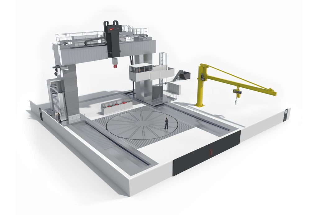
Described as Australia's largest machine tool, Starrag is supplying a Droop+Rein G 110TT HR100 C vertical gantry machine that is capable of handling both large hull elements and high-precision components for submarine construction. This large production machine features traversing paths of 45.93 x 42.65 x 11.48 ft (14,000 x 13,000 x 3,500 mm) in the X/Y/Z axes and an 36 ft (11 m) turntable.
Starrag is collaborating with the Australian machine tool manufacturer H&H Machine Tools Australia. H&H will manufacture key components, supply qualified personnel to help install the gantry and provide technical support for the entire life cycle of the machine, securing an ongoing role in servicing and maintenance in the future. Starrag will provide H&H with the necessary expertise through onsite training and quality control, transferring critical skills and autonomous ability to Australian industry.
According to Dr. Marcus Queins, manager for the large parts machining systems business unit at Starrag, the size and efficiency of the milling machine being supplied was of fundamental importance. The unit, which is also capable of turning components thanks to an integrated rotary table, is a "tried and tested" unit that is part of the Dörries range of lathes from the Starrag Group, he said.
According to the company, the Droop+Rein G 110 TT HR100 C owes its high precision to features such as the hydrostatic guides in all linear axes, as well as the thermo-symmetrical design of the milling unit with its integrated C axis. Milling heads can be changed automatically via a head change interface. Five different machining heads were selected to use on this project. The high-performance fork milling head features not only the ability to use the tool at any angle, but also the necessary prerequisites for heavy-duty machining on five axes simultaneously. Alternatively, the machine can be used with one straight and one angled 134HP (100-kW) milling head with a torque of 5531 ft-lb (7,500 Nm). A turret and a horizontal facing head are available for turning operations on the components.
The large, multifunctional machine supplied by Starrag from its Bielefeld, Germany, plant gives the operator optimum access. According to Starrag, the operator can reach any point on the workpiece thanks to the spacious cabin, which travels along the gantry and features a Siemens operator panel. The cabin can reach a height of 26ft (8m) and be moved towards the center of the table.
The gantry's robustness was a factor in its selection. Starrag was able to support this from the success of a previous project carried out in South Australia, for which Starrag supplied four machines for aircraft construction. The company believes that with proper maintenance, the machine will be operational throughout the entire run of the project. The first of the Attack Class submarines will be delivered in the early 2030's and continue into the early 2050's.
Starrag Group is a global technology leader in manufacturing high-precision machine tools for milling, turning, boring and grinding workpieces of metallic, composite and ceramic materials. Its North American headquarters can be reached at 859-534-5201 or visit them at www.starrag.com.


