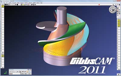
Gibbs and Associates announced that it has released GibbsCAM 2011, with dozens of enhancements to make NC programming easier and faster.
The software has enhanced feature and color recognition and preservation. To optimize efficiency and throughput, new tagging capabilities, combined with automatic feature recognition (AFR), allow users to control how GibbsCAM imports CAD models and manages part features and attributes. Color Modes were added to extend tagging and selection criteria of geometric elements: geometry, faces, surfaces and solids. When a part contains user-defined features, or elements tagged with a color attribute, users can switch among Color Modes to distinguish, select or isolate features or elements for manipulation, copying or machining.
As a result of these enhancements, upon opening CAD models, GibbsCAM can read attributes, then recognize and preserve them as attributes in the GibbsCAM part file. Colors are preserved as CAD colors in the part file, and hole features in the model are recognizable and usable as hole features within GibbsCAM hole operations.
Hole Making Capabilities for selecting, organizing, recognizing and drilling holes have been broadly enhanced. Hole Manager, a productivity tool within GibbsCAM, now includes a new Auto Wizard, which allows users to store default settings for reuse, quickly and easily, at any time. Using AFR, holes (and entities that resemble holes) are selectable by part face, set of faces, a hole's interior faces, or by coordinate system to which a hole feature is aligned. This streamlining enables users to automatically recognize and program hundreds of holes with as few as three mouse clicks, greatly simplifying and speeding up hole-making operations. Also, GibbsCAM now includes support for the full range of SolidWorks hole features.
Custom drill cycle options were added and, to reduce traverse and cycle time in drill cycles, a new check box enables reverse-order drilling.
Five-axis enhancements include various new drill cycle options, toolpath conversion, toolpath smoothing and additional machining styles. The new hole making features make programming drill cycles at off-axis orientations very easy and extremely fast. Programmers can choose drill, variable peck, tap and custom drill cycles.
A new Operation Modifier enables the conversion of 2.5- and 3-axis toolpaths for 5-axis machining, which allows use of shorter tools to achieve smoother toolpaths through tool-axis rotation when the work piece or tooling interferes with the tool holder.
Toolpath smoothing methods have been implemented for all types of geometry, both STL (triangle mesh) and traditional surface geometry, to improve both tilt and rotary toolpath smoothness.
Swarf cutting can now be specified two ways. Users can drive the tool using a) upper and lower curves, with or without a drive surface, or b) a parallel-to-curve strategy with tool-axis rotation. Also new is a 5-axis trimming strategy that uses wireframe geometry.
Support for B-axis (tilting live tooling) was added to enable programming 5-axis milling with Y-axis offsets on lathes and multi-task machines equipped with a live-tooling B-axis.
Contact Details
Related Glossary Terms
- computer-aided design ( CAD)
computer-aided design ( CAD)
Product-design functions performed with the help of computers and special software.
- gang cutting ( milling)
gang cutting ( milling)
Machining with several cutters mounted on a single arbor, generally for simultaneous cutting.
- milling
milling
Machining operation in which metal or other material is removed by applying power to a rotating cutter. In vertical milling, the cutting tool is mounted vertically on the spindle. In horizontal milling, the cutting tool is mounted horizontally, either directly on the spindle or on an arbor. Horizontal milling is further broken down into conventional milling, where the cutter rotates opposite the direction of feed, or “up” into the workpiece; and climb milling, where the cutter rotates in the direction of feed, or “down” into the workpiece. Milling operations include plane or surface milling, endmilling, facemilling, angle milling, form milling and profiling.
- numerical control ( NC)
numerical control ( NC)
Any controlled equipment that allows an operator to program its movement by entering a series of coded numbers and symbols. See CNC, computer numerical control; DNC, direct numerical control.
- swarf
swarf
Metal fines and grinding wheel particles generated during grinding.
- tap
tap
Cylindrical tool that cuts internal threads and has flutes to remove chips and carry tapping fluid to the point of cut. Normally used on a drill press or tapping machine but also may be operated manually. See tapping.
- toolpath( cutter path)
toolpath( cutter path)
2-D or 3-D path generated by program code or a CAM system and followed by tool when machining a part.


