With hyperCAD-S, Open Mind Technologies AG says it has created a CAD solution that is optimally matched to the tasks of an NC programmer. hyperCAD-S was extended to include the ‘Solids' module in the new 2014.2 version of hyperMILL. The module makes it possible to import and create solid models and modify them quickly with direct modelling. CAD-S, the CAD system from OPEN MIND Technologies AG, is a proprietary development. Even the core of the system was developed in-house.
"This allows us to quickly respond to market demands as well as requirements resulting from the further development of hyperMILL," says Wolfgang Weiss, product manager for CAD at OPEN MIND.
Up to now, hyperCAD-S has worked with surfaces. The software has now received a solid extension. This results in total consistency between surfaces and solids. Everything is now one part, one view on the solid model.
NC programmers frequently have to work with external data. To import this data reliably, NC programmers require high-performance interfaces. The interface package in hyperCAD-S includes IGES, STEP, DXF/ DWG, CATIA V4 and V5, Parasolid, Siemens NX, PTC Creo and SOLIDWORKS. It is also possible to import point clouds.
The selection of individual geometry parts is very important for subsequent machining. To this end, the new version features comprehensive selection options for faces and curves:
• Limited faces
• Tangential faces
• Chamfer
• Fillets
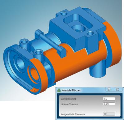
• Coaxial faces
• Coplanar faces
• Optimised chain selection
"Smart selector technology enables the simple, combined selection of surface areas and curves. Users can now select and use the required milling areas for hyperMILL much faster," explains Wolfgang Weiss.
CAM programmers do not require geometry or feature history for solid modelling. This is particularly advantageous when it comes to processing external data. Users can now use direct modelling in hyperCAD-S to modify geometries or surfaces. The model geometry can be machined directly. Simply select the desired features or surfaces and modify them by dragging the handles and manipulators. The user does not have to consider the construction history or any constraints. This significantly shortens machining times, as users do not have to take any parametric dependencies into account.
The functions presented here can be used on native and imported geometries.
Creating solids can take place in the traditional manner by linearly extruding a contour or by rotating a contour. This makes it possible to create linear slots and rotational slots.
There are also holes, patterns, fillets and chamfers as basic entities.
Users that frequently work with the same, recurring features are sure to take advantage of the new zone feature. This enables users to create user-specific features. Zones can be transformed, copied, deleted or stored as a user-defined selection.
It is possible to modify everything that has been created. There are also Boolean operations such as union, difference, intersection and split.
Features can also be changed through deletion, new definition, mirroring, extraction and generation of patterns.
All of these options enable CAM programmers to make necessary changes to CAD models, such as when creating mean tolerances or additions as well as when constructing clamping tools or fixtures.
The software is designed for 64-bit multi-application and well suited for running on modern multi-core processors.
Related Glossary Terms
- computer-aided design ( CAD)
computer-aided design ( CAD)
Product-design functions performed with the help of computers and special software.
- computer-aided manufacturing ( CAM)
computer-aided manufacturing ( CAM)
Use of computers to control machining and manufacturing processes.
- gang cutting ( milling)
gang cutting ( milling)
Machining with several cutters mounted on a single arbor, generally for simultaneous cutting.
- milling
milling
Machining operation in which metal or other material is removed by applying power to a rotating cutter. In vertical milling, the cutting tool is mounted vertically on the spindle. In horizontal milling, the cutting tool is mounted horizontally, either directly on the spindle or on an arbor. Horizontal milling is further broken down into conventional milling, where the cutter rotates opposite the direction of feed, or “up” into the workpiece; and climb milling, where the cutter rotates in the direction of feed, or “down” into the workpiece. Milling operations include plane or surface milling, endmilling, facemilling, angle milling, form milling and profiling.
- numerical control ( NC)
numerical control ( NC)
Any controlled equipment that allows an operator to program its movement by entering a series of coded numbers and symbols. See CNC, computer numerical control; DNC, direct numerical control.
- solid model
solid model
3-D model created using “building blocks.” This is the most accurate way of representing real-world objects in CAD.


