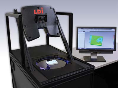
Laser Design Inc. announced the unveiling of its newest and most automated inspection-grade 3D scanning system, the SURVEYOR Auto Gage 3D. Laser Design President, C. Martin Schuster commented, "The SURVEYOR Auto Gage 3D Scanning System was developed to provide a totally automated, extremely easy to use 3D inspection-grade system for either shop floor or office environments with accuracy to 25µm (0.001")."
Two goals are realized with the Auto Gage 3D system: Complete high-speed part inspections in minutes and minimal operator training.
Schuster continued, "Geomagic software's unique level of inspection automation has enabled Laser Design to open the age of entire part 3D inspections with 'microwave oven' push-button simplicity of use."
Operator input is minimal and training is fast, which means the Auto Gage 3D can be up and running in a very short timeframe. First article part inspections, incoming part inspections, and sample part inspections on the shop floor can now be performed by machine attendant-level employees.
The Auto Gage 3D Scanning System uses structured light projection technology from one scanner head to capture all viewable surfaces of small- to medium-sized objects. With a work envelope of 6" x 6" x 4" (Auto Gage 4100) or 10" x 10" x 5" (Auto Gage 6100) the automated system is versatile enough for inspection and reverse engineering applications, and speedy enough for factory-floor verification uses. Yielding premium precision, system scans are accurate to +/-0.001" (0.025mm).
The built-in system PC provides full control for scanning and optional data processing. The system is pre-configured with one 3D scanning head. Highly automated, the Auto Gage 3D requires only minimal training to perform scans with the one-button scan operation. Most parts do not require fixturing unless they are unstable in the desired orientation.
Typically scanned objects include small- to medium-sized parts made of plastic, metal, and rubber, and cast, molded, forged, and machined parts. Parts can be inspected quickly and efficiently because setups are saved as reusable templates. Items can be inspected and re-qualified in just hours, preventing downtime and costly delays with slow manual measurement methods. Extrusion profiles can be sample inspected to ensure accuracy and uniformity. Data outputs include .STL, .OBJ, .PLY, and .ASC formats.
The digitized data can be processed further with optional meshing, surface modeling, color error mapping, and inspection software from Laser Design's solution partner, Geomagic. Fully automated inspection reports can be created and reports comparing the scan data to CAD models can be immediately viewed by the operator to make a fast Go/No Go decision of shape verification.
Contact Details
Related Glossary Terms
- computer-aided design ( CAD)
computer-aided design ( CAD)
Product-design functions performed with the help of computers and special software.
- extrusion
extrusion
Conversion of an ingot or billet into lengths of uniform cross section by forcing metal to flow plastically through a die orifice.
- work envelope
work envelope
Cube, sphere, cylinder or other physical space within which the cutting tool is capable of reaching.


