Safely and efficiently back spotfacing and back counterboring large holes for applications such as gas and steam turbines and wind turbine gearboxes can be a challenge. This is because the workpiece weight often prevents the part from being optimally rotated, or positioned, for a machining operation that faces away from the spindle side of the bore. In addition, the machine may not have enough axes to apply a conventional tool, such as a milling tool, according to Bernd Aschenbach, a scientist at GFE - Gesellschaft für Fertigungstechnik und Entwicklung Schmalkalden e.V. (Society of Production Technology and Development).
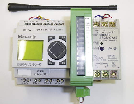
The stationary interface, or base station, for GFE’s mechatronic tool can be located in a machine’s control cabinet.
Therefore, GFE developed a prototype mechatronic cutting tool for these applications, which uses bidirectional telemetry to gather information about tool status during cutting. (Mechatronics incorporates mechanical and electronics engineering concepts.) “The use of mechatronic tools with integrated sensor-monitored actuators can help reduce the amount of work required when back counterboring and back spotfacing on large machining centers while retaining high levels of process dependability,” Aschenbach said.
Depending on the application, he noted a mechatronic tool can use magnetic Hall and eddy current sensors, optical sensors such as cameras and lasers, and other sensors to monitor and influence the machining process, but they have no direct influence on the tool. For example, two Hall sensor integrated circuits can monitor the end positions of a hydraulic cutting drive, or piston, which tilts the cutting edges. Coolant actuates the piston, causing the insert holders to pivot outward, and the tool can be guided axially back through the pilot bore after the coolant is turned off, causing the insert holders to pivot inward.
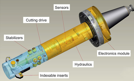
A 3-D model of the prototype mechatronic cutting tool for back spotfacing and back counterboring.
The data is transmitted to the stationary interface, or base station, at a frequency of 430MHz, and signals from the interface can control the machine, such as stopping the machine when a malfunction occurs. “Our prototype transmits the angular positions of the cutting inserts,” Aschenbach said, adding that the interface can be located in a machine’s control cabinet.
With systematic testing, he added that GFE plans to explore commercial feasibility of the prototype tool.
For more information, contact GFE, Schmalkalden, Germany, at 011-49-36-83-69-00-0 or www.gfe-net.de. CTE
Related Glossary Terms
- 3-D
3-D
Way of displaying real-world objects in a natural way by showing depth, height and width. This system uses the X, Y and Z axes.
- centers
centers
Cone-shaped pins that support a workpiece by one or two ends during machining. The centers fit into holes drilled in the workpiece ends. Centers that turn with the workpiece are called “live” centers; those that do not are called “dead” centers.
- coolant
coolant
Fluid that reduces temperature buildup at the tool/workpiece interface during machining. Normally takes the form of a liquid such as soluble or chemical mixtures (semisynthetic, synthetic) but can be pressurized air or other gas. Because of water’s ability to absorb great quantities of heat, it is widely used as a coolant and vehicle for various cutting compounds, with the water-to-compound ratio varying with the machining task. See cutting fluid; semisynthetic cutting fluid; soluble-oil cutting fluid; synthetic cutting fluid.
- counterboring
counterboring
Enlarging one end of a drilled hole. The enlarged hole, which is concentric with the original hole, is flat on the bottom. Counterboring is used primarily to set bolt heads and nuts below the workpiece surface.
- gang cutting ( milling)
gang cutting ( milling)
Machining with several cutters mounted on a single arbor, generally for simultaneous cutting.
- milling
milling
Machining operation in which metal or other material is removed by applying power to a rotating cutter. In vertical milling, the cutting tool is mounted vertically on the spindle. In horizontal milling, the cutting tool is mounted horizontally, either directly on the spindle or on an arbor. Horizontal milling is further broken down into conventional milling, where the cutter rotates opposite the direction of feed, or “up” into the workpiece; and climb milling, where the cutter rotates in the direction of feed, or “down” into the workpiece. Milling operations include plane or surface milling, endmilling, facemilling, angle milling, form milling and profiling.
- spotfacing
spotfacing
Similar to counterboring except that, in spotfacing, material around the original hole is cut. Application example: the recessed area into which a washer fits. See counterboring; countersinking.
Author

Alan holds a bachelor’s degree in journalism from Southern Illinois University Carbondale. Including his 20 years at CTE, Alan has more than 30 years of trade journalism experience.


